
Technical data


OM 1191 27
Parameters
Table 11 continued: Group 16: System Controls
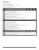
1608 START ENABLE 1 -6…7 1 4 (DI4)
Selects the source of the start enable 1 signal.
Note: Start enable functionality differs from the run enable functionality.
0 = NOT SEL – Allows the drive to start without an external start enable signal.
1 = DI1 – Denes digital input DI1 as the start enable 1 signal.
• This digital input must be activated for start enable 1 signal.
• If the voltage drops and de-activates this digital input, the drive will coast to stop and show alarm 2021 on the panel display.
The drive will not start until
start enable 1 signal resumes.
2…6 = DI2…DI6 – Denes digital input DI2…DI6 as the start enable 1 signal.
• See DI1 above.
7 = COMM – Assigns the eldbus Command Word as the source for the start enable 1 signal.
• Bit 2 of the Command Word 2 (parameter 0302) activates the start disable 1 signal.
• See eldbus user’s manual for detailed instructions.
-1 = DI1(INV) – Denes an inverted digital input DI1 as the start enable 1 signal.
-2…-6 = DI2 (INV)…DI6(INV) – Denes an inverted digital input DI2…DI6 as the start enable 1 signal.
• See DI1 (INV) above.
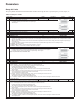
1611 PARAMETER VIEW 0, 1 1
0
(DEFAULT)
Selects the parameter view, i.e. which parameters are shown.
Note: This parameter is visible only when it is activated by the optional FlashDrop device. FlashDrop is designed for fast copying of parameters to unpowered
drives. It allows easy customization of the parameter list, e.g. selected parameters can be hidden. For more information, see MFDT-01 FlashDrop User’s
Manual (3AFE68591074 [English]). FlashDrop parameter values are activated by setting parameter 9902 to 31 (LOAD FD SET).
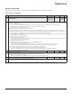
0 = DEFAULT – Complete long and short parameter lists are shown.
1 = FLASHDROP – FlashDrop parameter list is shown. Does not include short parameter list. Parameters that are hidden by the FlashDrop device are not
visible.