
Technical data

20 OM 1191
Parameters
Group 10: Start/Stop/Dir
This group:
• Denesexternalsources(EXT1andEXT2)forcommandsthatenablestart,stopanddirectionchanges
• Locks direction or enables direction control.
To select between the two external locations use the next group (parameter 1102).
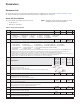
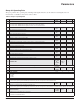
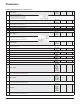
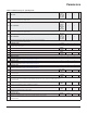
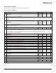
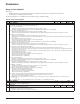
Table 8: Group 10: Start/Stop/Dir
Code Description Range Resolution Default S
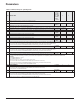
1001 EXT1 COMMANDS 0…14 1 1 (DI1)
Denes external control location 1 (EXT1) – the conguration of start, stop and direction commands.
0 = NOT SEL – No external start, stop and direction command source.
1 = DI1 – Two-wire Start/Stop.
• Start/Stop is through digital input DI1 (DI1 activated = Start; DI1 de-activated = Stop).
• Parameter 1003 denes the direction. Selecting 1003 = 3 (REQUEST) is the same as 1003 = 1 (FORW
ARD).
2 = DI1,2 – Two-wire Start/Stop, Direction.
• Start/Stop is through digital input DI1 (DI1 activated = Start; DI1 de-activated = Stop).
• Direction control [requires parameter 1003 = 3 (REQUEST)] is through digital input DI2 (DI2 activated = Reverse; de-activated = Forward).
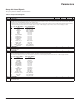
3 = DI1P,2P – Three-wire Start/Stop.
• Start/Stop commands are through momentary push-buttons (the P stands for “pulse”).
• Start is through a normally open push-button connected to digital input DI1. In order to start the drive, the digital input DI2 must be activated prior to the
pulse in DI1.
• Connect multiple Start push-buttons in parallel.
• Stop is through a normally closed push-button connected to digital input DI2.
• Connect multiple Stop push-buttons in series.
• Parameter 1003 denes the direction. Selecting 1003 = 3 (REQUEST) is the same as 1003 = 1 (FORW
ARD).
4 = DI1P,2P,3 – Three-wire Start/Stop, Direction.
• Start/Stop commands are through momentary push-buttons, as described for DI1P,2P
.
• Direction control [requires parameter 1003 = 3 (REQUEST)] is through digital input DI3 (DI3 activated = Reverse; de-activated = Forward).
5 = DI1P,2P,3P – Start Forward, Start Reverse and Stop.
• Start and Direction commands are given simultaneously with two separate momentary push-buttons (the P stands for “pulse”).
• Start Forward command is through a normally open push-button connected to digital input DI1. In order to start the drive, the digital input DI3 must be
activated prior to the pulse in DI1.
• Start Reverse command is through a normally open push-button connected to digital input DI2. In order to start the drive, the digital input DI3 must be
activated during the pulse in DI2.
• Connect multiple Start push-buttons in parallel.
• Stop is through a normally closed push-button connected to digital input DI3.
• Connect multiple Stop push-buttons in series.
• Requires parameter 1003 = 3 (REQUEST).
6 = DI6 – Two-wire Start/Stop.
• Start/Stop is through digital input DI6 (DI6 activated = Start; DI6 de-activated = Stop).
• Parameter 1003 denes the direction. Selecting 1003 = 3 (REQUEST) is the same as 1003 = 1 (FORW
ARD).
7 = DI6,5 – Two-wire Start/Stop/Direction.
• Start/Stop is through digital input DI6 (DI6 activated = Start; DI6 de-activated = Stop).
• Direction control [requires parameter 1003 = 3 (REQUEST)] is through digital input DI5. (DI5 activated = Reverse; de-activated = Forward).
8 = KEYPAD – Control Panel.
• Start/Stop and Direction commands are through the control panel when EXT1 is active.
• Direction control requires parameter 1003 = 3 (REQUEST).
9 = DI1F,2R – Start/Stop/Direction commands through DI1 and DI2 combinations.
• Start forward = DI1 activated and DI2 de-activated.
• Start reverse = DI1 de-activated and DI2 activated.
• Stop = both DI1 and DI2 activated, or both de-activated.
• Requires parameter 1003 = 3 (REQUEST).
10 = COMM – Assigns the eldbus Command Word as the source for the start/stop and direction commands.
• Bits 0, 1, 2 of Command Word 1 (parameter 0301) activates the start/stop and direction commands.
• See Fieldbus user’s manual for detailed instructions.
11 = TIMED FUNC 1. – Assigns Start/Stop control to Timed Function 1 (Timed Function activated = START; Timed Function de-activated = STOP).
See on page 35
.
12…14 = TIMED FUNC 2…4 – Assigns Start/Stop control to Timed Function 2…4. See TIMED FUNC 1 above.
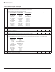
1002 EXT2 COMMANDS 0…14 1 1 (DI1)
Denes external control location 2 (EXT2) – the conguration of start, stop and direction commands.
• See parameter 1001 EXT1 COMMANDS above.
1003 DIRECTION 1…3 1
1
(FORWARD)
Denes the control of motor rotation direction.
1 = FORWARD – Rotation is xed in the forward direction.
2 = REVERSE – Rotation is xed in the reverse direction.
3 = REQUEST – Rotation direction can be changed on command.