
Troubleshooting guide


OM 931-3 / Page 9 of 28
Control Inputs (HP, LP, SLTS, COF, U, E, O)
The control inputs are High Pressure (HP), Low Pressure
(LP), Suction Line Temperature Sensor (SLTS), Condensate
Overow (COF), Unoccupied (U), and Remote Shutdown
(E). The state of each control input during unoccupied mode
during normal operation is as follows:
■ High / Low Pressure (HP, LP): energizes, switch is closed
(no fault).
■ Suction Line Temperature Sensor (SLTS): greater than
setpoint unit operates (no fault).
■ Condensate Overow (COF): sensing no condensate
water (no fault).
■ Unoccupied (U): energizes (signal provided).
■ Remote Shutdown (E): de-energizes (no signal).
■ Tenant Override (O): see "Tenant Override" on page 11.
Control Outputs {A and IV/PR (H8)}
The control outputs provided by the MicroTech III unit
controller are Alarm Fault (A) and Isolation Valve / Pump
Request (IV/PR (H8)). The operation of the control outputs
during unoccupied mode is the same as in occupied mode
(see "Occupied Operation" on page 7).
Fan Operation
The G terminal has no effect during unoccupied mode.
Cooling Mode
Cooling operation is not available during unoccupied mode.
Heating Mode
The W2 terminal controls the unoccupied Heating Mode of
operation. When the W2 terminal is energized the following
occurs:
1. The fan energizes.
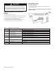
2. The IV/PR (H8) control output energizes or deenergizes
depending on H8 terminal wiring (refer to Table 1 on page
4 & Figure 1, page 5).
3. The compressor will start 30 seconds later.
4. If the reversing valve output is de-energized, the reversing
valve output will energize within 5 to 20 seconds of
the compressor being energized, depending on the
conguration of jumpers JP7 and JP8.
When the W2 terminal is de-energized the following occurs:
1. The compressor de-energizes.
2. The IV/PR (H8) control output energizes or deenergizes
depending on H8 terminal wiring (refer to Table 1 on page
4 & Figure 1, page 5).
3. The reversing valve remains energized.
Note: To prevent compressor cycling, the required
minimum on/off time default is 180 seconds. This
may cause the compressor time delay to be longer
than indicated above.
Additional Operating Modes
Brownout
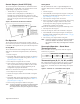
Board LED Status – Brownout
Y
ellow
Green
Red
Of
f Flash
Of
f
Brownout condition is provided to protect the water source
heat pump’s motor electrical damage due to low voltage
conditions.
The MicroTech III unit controller is designed to monitor the
24VAC power supply to the board. If the line voltage supplied
to the water source heat pump drops, the 24VAC supply to the
control board will also drop. When the line voltage supplied
to the unit drops below approximately 80% of the unit name-
plate rated value, the controller goes into brownout condition.
The controller remains in brownout condition until line volt-
age returns to approximately 90% of the unit nameplate value.
When in brownout condition, thermostat and control inputs
have no affect upon unit operation. No faults or modes have
higher priority than a brownout fault condition. Remote
shutdown and brownout conditions have the same level of
priority. See "Priority of Faults and Modes" on page 12 and
Table 3 on page 12.
When the unit is in brownout condition the following occurs:
1. The compressor de-energizes.
2. The reversing valve de-energizes.
3. The fan de-energizes.
4. Fault terminal (A) de-energizes (fault). A to C will be used
to indicate an alarm signal.
When the line voltage supplied to the unit returns to accept-
able levels (~90% of nameplate) the controller returns to the
current mode.
Remote Shutdown
Board LED Status – Remote Shutdown
Y
ellow
Green
Red
Flash
Of
f
Of
f
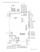
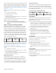
When the E terminal is grounded, the MicroTech III unit
controller enters remote shutdown mode. Remote shutdown
is provided so that when properly connected to a building
automation system, remote switch, etc., the E terminal can be
used to shut down the water source heat pump.
Figure 5: Terminal "E" - Grounded for Remote Shutdown