
Troubleshooting guide


OM 931-3 / Page 7 of 28
General Use and Information
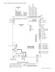
The MicroTech III unit controller is provided with two drive
terminals, R (24VAC), and C (0VAC) that can be used to
drive the thermostat inputs (G, Y1, Y2, W1, and W2) and
control inputs (U, E and O). Any combination of or single
board drive terminal (R, or C) may be used to operate the Mi-
croTech III’s unit controller or thermostat inputs. Some of the
control inputs are used within the Water Source Heat Pump
and not accessible to the end user without a eld service tool
(laptop with appropriate software).
Typically the MicroTech III unit controller's R (24VAC)
terminal is used to drive the board’s thermostat inputs and
control inputs by connecting it to the R terminal of an indus-
try standard thermostat. The control outputs of the standard
thermostat are then connected to the MicroTech III unit
controller's thermostat inputs and control inputs as needed.
Any remaining board input(s) may be operated by additional
thermostat outputs or remote relays (dry contacts only).
All MicroTech III unit controller inputs must be operated by
dry contacts powered by the control board’s power terminals.
No solid state devices (Triacs) may be used to operate Micro-
Tech III unit controller inputs. No outside power sources may
be used to operate MicroTech III. All units must be properly
grounded per local code requirements. See the Installation
and Maintenance bulletin specic to your Water Source Heat
Pump.
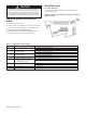
Occupied Operation
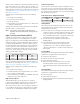
Board LED Status – Occupied
Y
ellow
Green
Red
Of
f
On
Of
f
The board will be in occupied mode if the unoccupied
terminal (U) is de-energized.
Thermostat Inputs (G, Y1, Y2, W1 and W2)
Thermostat inputs used during occupied operation are G, Y1,
and W1, which when energized will activate the Fan Only,
Cooling Mode, and Heating Mode respectively. Input W2
and Y2 work the same as W1 and Y2 respectively for single
circuit units in occupied mode. For information on W2 and
Y2 for dual circuit units, refer to "Dual Circuit Units" on page
17.
The MicroTech III unit controller is congured so that when
either the Y1 or W1 input is energized the unit fan is also
activated with Cooling or Heating Modes. In other words,
energizing Y1 and G together will have the same effect as en-
ergizing just Y1. The W1 input has priority over the Y1 input.
In situations when both inputs W1 and Y1 become energized
(unlikely) in any order the unit will go into the Heating Mode
as described below:
1. If the unit is in Cooling Mode, Y1 is energized. If W1
becomes energized and remains energized, the following
will occur:
• The compressor de-energizes.
• The compressor restarts at 180 seconds (powerup
delay timer).
• The reversing valve output energizes within 5 to 20
seconds of the compressor being energized (Heating
Mode position), depending on the conguration of
jumpers JP7 and JP8.
2. If the unit is in Cooling Mode, Y1 is energized. If W1
becomes energized momentarily, the controller de-
energizes the compressor for 180 seconds (shortcycle
timer) and then returns to the cooling mode.
3. However, if the unit is in Heating Mode, W1 is energized.
If Y1 becomes energized the unit remains in Heating
Mode.
4. Y2 is the second stage cooling, and applies to dual
compressor units.
Control Inputs (HP, LP, SLTS, COF, U, E, O)
The control inputs are High Pressure (HP), Low Pressure
(LP), Suction Line Temperature Sensor (SLTS), Condensate
Overow (COF), Unoccupied (U), and Remote Shutdown
(E). The control inputs are in normal states during occupied
mode. The state of each control in occupied mode during
normal operation is as follows:
• High / Low Pressure (HP, LP): energizes, switch is closed
(no fault).
• Suction Line Temperature Sensor (SLTS): temperature
sensor on the suction line which provides low temperature
protection. Condensate Overow(COF):sensing no
condensate water (no fault).
• Unoccupied (U): de-energized (no signal).
• Remote Shutdown (E): de-energized (no signal).
• Tenant Override (O): has no effect in occupied mode.