
Troubleshooting guide


Page 6 of 28 / OM 931-3
Initial Power-Up
Pre start check list:
A random start delay time between 180 and 240 seconds is
generated at power up.
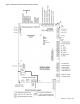
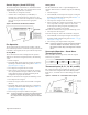
Figure 2: Location of Configuration Jumpers on the Base
Board Controller
CAUTION
The MicroTech III circuit board incorporates static sensitive de-
vices. A static charge from touching the device can damage the
electronic components. To help prevent damage during service,
use static discharge wrist straps.Static discharge wrist straps
are grounded to the heat pump chassis through a 1 Mohm resistor.
Replacing a MicroTech III circuit
board:
1. Connect wrist strap to unit.
2. Remove faulty board and place on static protected surface.
3. Remove replacement board from static protected bag.
Do not touch circuit board; hold by edges.
4. Holding board in grounded hand, install board in unit.
5. Insert faulty board in empty static bag for return.
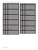
Table 2: Configuration Jumper Settings
Jumper Description Options
JP1 Mode
Open for normal operation mode
Shorted for service/test operation mode
JP2 Fan operation only applies to Open for continuous fan operation
network controls Shorted for cycling fan operation
JP3 Freeze protection
Open for water freeze protection
Shorted for antifreeze protection
JP4 Future spare Future spare
JP5 Set point adjustment range only Open for adjustment range of -3.0° to +3.0° F
applies to network controls with a Shorted for 50° to 90° F adjustment range
room temperature sensor
JP6 Room control type
Open for thermostatic room control
Shorted for room temperature sensor control, MicroTech III only
JP7 Future spare Future spare
JP8 Future spare Future spare