
Troubleshooting guide

OM 931-3 / Page 15 of 28
Microtech® III Unit Controller
Interface to External Equipment
■ The MicroTech III unit controller’s thermostat input
terminals may be directly interfaced with any standard
or night setback thermostat that uses mechanical dry
contacts. Power cannot be supplied from the water
source heat pump for electronic thermostats that require a
separate power supply for their internal operation except
hose provided by Daikin McQuay. Only thermostats
offered by Daikin McQuay are proven to operate properly
with the MicroTech III unit controller. Daikin McQuay
makes no guarantees about any other thermostat or control
device interfaced by the end user with the MicroTech III
unit controller.
■ Care must be used to isolate all external power sources
from the MicroTech III unit controller to prevent ground
loops and other unpredictable electrical problems. Only
dry mechanical contacts should be used to operate
or interface with the MicroTech III unit controller’s
thermostat and or control inputs. Use mechanical relays
to isolate two power systems when external equipment
with its own power supply is used to interface with or
control the MicroTech III unit controller’s thermostat and
or control inputs. For example, if you have a Building
Automation System (BAS), controller, etc., and you
wish to use a digital output from the building automation
system or controller that is internally powered, then you
must use an additional mechanical relay (not supplied
by Daikin McQuay) to isolate the MicroTech III unit
controller.
■ Due to the nature of triacs and other solid state devices,
triacs cannot be directly used to operate the MicroTech
III’s unit controller’s thermostat or control inputs. To
interface triacs or other solid state switching devices to the
MicroTech III unit controller inputs, separate them from
the board using mechanical relays. To do this, use the
triac or solid state device to drive a mechanical relay (not
supplied by Daikin McQuay), then use the mechanical
relay’s dry contacts to drive the desired MicroTech III unit
controller input.
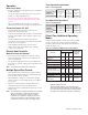
■ The MicroTech III unit controller’s valve or pump request
terminal {IV/PR (H8)} is an output signal to external
devices to allow water ow as required by the heat pump.
The IV/PR (H8) terminal follows compressor operation
inversely if connected to the normally open terminal and
simultaneously when connected to the normally closed
terminal. The IV/PR (H8) terminal can be used as a signal
to an external pump or valve to enable ow to the unit.
The compressor start is delayed for 30 seconds after the
IV/PR (H8) output is energized.
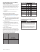
Table 5: IV/PR(H8) Terminal and Compressor Operation
IV/PR(H8)
Compressor On
Compressor Off
Normally Open
24 V
AC
0 V
AC
Normally Closed
0 V
AC
24 V
AC
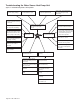
Appendix A
Operation and Maintenance of I/O
Expansion Module
Introduction
The I/O Expansion Module is a eld-installed option. It is an
extension of the main board and provides extra functionality
to the MicroTech III control system.
The I/O Expansion Module has 4 main purposes:
■ The MicroTech III unit controller in combination with the
I/O Expansion Module will be the standard control system
for two stage Water Source Heat Pump equipment. For
example: large vertical units.
■ The I/O Expansion Module has outputs to control electric
heat on a standard Water Source Heat Pump.
■ The I/O Expansion Module has outputs for multi-speed
fans on a standard Water Source Heat Pump.
■ The I/O Expansion Module has an independent LED
annunciator to identify operational fault conditions on
second stage equipment.
Adding an I/O Expansion Module (with an interconnect
cable) to the main controller allows two stage operation of the
water source heat pump.
Features
Second Circuit
■ High pressure switch
■ Low pressure switch
■ Low suction line temperature sensor
■ Compressor output
■ Reversing valve
Standard Heat Pumps / Single Circuit Units
■ Monitors entering water temperature for boilerless
electric heat control
■ Outputs for medium and high speed fan controls