Operation & Maintenance Data OM 931-3 Group: WSHP Part Number: 669479403 Date: May 2012 MicroTech® III Unit Controller for Water Source Heat Pump Units ©2012 McQuay International • 800.432.1342 • www.daikinmcquay.
Contents Introduction...........................................................................3 Replacing a MicroTech III circuit board:.............................6 Initial Power-Up....................................................................6 General Use and Information..............................................7 Occupied Operation...........................................................7 Thermostat Inputs (G, Y1, Y2, W1 and W2)......................
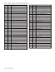
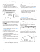
Table 1: MicroTech III Unit Controller Terminals & Descriptions H1 - 1 24 24 VAC Power Input H7 - 6 Red-Green-Yellow LED Common H1 - 2 C 24 VAC Common H8 - 1 1 Isolation Valve/Pump Request Relay N/O H2 - 1 SL1 Fan Output - Switched L1 H8 - 2 Isolation Valve/Pump Request Relay N/C H2 - 2 Blank Terminal H8 - 3 24 VAC Common H2 - 3 N Fan Neutral H9 - 1 Return Air Temperature Signal H3 - 1 HP1-1 High Pressure Switch 1 Input Terminal 1 H9 - 2 Return Air Temperature Common
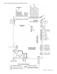
Figure 1: MicroTech III Unit Controller Terminal Locations OM 931-3 / Page 5 of 28
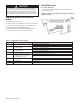
CAUTION The MicroTech III circuit board incorporates static sensitive devices. A static charge from touching the device can damage the electronic components. To help prevent damage during service, use static discharge wrist straps.Static discharge wrist straps are grounded to the heat pump chassis through a 1 Mohm resistor. Initial Power-Up Pre start check list: A random start delay time between 180 and 240 seconds is generated at power up.
General Use and Information The MicroTech III unit controller is provided with two drive terminals, R (24VAC), and C (0VAC) that can be used to drive the thermostat inputs (G, Y1, Y2, W1, and W2) and control inputs (U, E and O). Any combination of or single board drive terminal (R, or C) may be used to operate the MicroTech III’s unit controller or thermostat inputs.
Control Outputs {A and IV/PR (H8)} The control outputs are Alarm Fault (A) and Isolation Valve / Pump Request {IV/PR (H8)}. The operation of the control outputs during occupied mode is as follows: • Alarm Fault (A): energized (no fault). • Isolation Valve / Pump Request {IV/PR (H8)}: is selectable to be energized when the compressor is off (normally closed), or when the compressor is on (normally open), by moving the wire lead to the appropriate terminal.
Control Inputs (HP, LP, SLTS, COF, U, E, O) The control inputs are High Pressure (HP), Low Pressure (LP), Suction Line Temperature Sensor (SLTS), Condensate Overflow (COF), Unoccupied (U), and Remote Shutdown (E). The state of each control input during unoccupied mode during normal operation is as follows: ■ High / Low Pressure (HP, LP): energizes, switch is closed (no fault). ■ Suction Line Temperature Sensor (SLTS): greater than setpoint unit operates (no fault).
When in remote shutdown (E terminal grounded), thermostat and control inputs have no affect upon unit operation. No faults or modes have higher priority than remote shutdown. Remote shutdown and brownout condition have the same level of priority. See "Priority of Faults and Modes" on page 12 and Table 3 on page 12. When the unit is in remote shutdown mode, the following occurs: 1. The compressor de-energizes. 2. The reversing valve de-energizes. 3. The fan de-energizes. 4.
Condensate Overflow Yellow On Tenant Override Board LED Status – Condensate Overflow Red Green Off Off Note: The MicroTech III unit controller's condensate sensor is designed to detect excessively high condensate water levels in the drain pan. When high condensate water levels are detected during cooling mode, the controller enters into condensate fault mode. The fan operates normally during the condensate overflow fault mode. Some faults and modes have higher priority than condensate overflow mode.
Fan Operation during most Modes, Faults and Shutdowns The MicroTech III unit controller allows fan operation during most modes, faults and shutdowns to facilitate maximum space comfort and control. However, the fan does not operate during brownout condition. During most modes, faults, or shutdowns the fan will operate under the following conditions: 1. In occupied modes, the thermostat inputs G, Y1, or W1 are energized. 2. In unoccupied modes, the thermostat input W2 is energized.
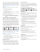
Figure 6: MicroTech III Unit Controller LED Status and Faults Troubleshooting Reference Read Outputs Check Timers Yes Brownout No Yes High Pressure Yes Low Pressure No Start Compressor No Yes Yes Yes Yes 30 Second Time Delay Low Suct Temp Sensor No Low Suct Temp Request for Water Flow No Room Temp Sensor Failure No R-W1 No Yes R -Y 1 No Condensate Overflow Stop Compressor Flash Green LED Stop Compressor Flash Red LED Stop Compressor Flash Yellow LED Flash Green LED Solid Red LED Stop Co
Troubleshooting the Water Source Heat Pump Unit Figure 7: Troubleshooting Guide - Unit Operation Low voltage, check power supply voltage Fuse may be blown, circuit breaker is open Wire may be loose or broken.
Microtech® III Unit Controller Interface to External Equipment ■ The MicroTech III unit controller’s thermostat input terminals may be directly interfaced with any standard or night setback thermostat that uses mechanical dry contacts. Power cannot be supplied from the water source heat pump for electronic thermostats that require a separate power supply for their internal operation except hose provided by Daikin McQuay.
Initial Power up Figure 8: I/O Expansion Board Configuration Jumper Terminals Table 6: I/O Expansion Board Configuration Jumper Settings Jumper Description Options Open for single compressor JP1 Number of Compressors Shorted for dual compressor Open to disable reheat JP2 Hot Gas/Water Reheat Shorted to enable reheat JP3 and JP4 open for no supplemental heat JP3 & JP4 Supplemental Heat Type JP3 open, JP4 shorted for boilerless electric heat JP3 and JP4 shorted is an invalid setting JP
Operation Three-Speed Fan Operations Dual Circuit Units Table 7: Three-Speed Fan • • • • Provides standard lead / lag operation for two compressors in dual circuit units Circuit one will come on first when there is any call for heating or cooling at the main board The second circuit will be enabled after the interstage timer has expired.
Second Circuit Faults With the addition of the second circuit the fault recovery and reset table has new faults for the second circuit (Table 10).
Appendix B MicroTech III Unit Controller with LonWorks® Communication Module For installation and operation information on LonWorks Communication Module and other ancillary control components, see: ■ IM 927 - MicroTech III Water Source Heat Pump LonWorks Communication Module. ■ IM 933 - LonMaker Integration Plug-in Tool: For use with the MicroTech III Unit Controller.
MicroTech III Controller with BACnet® Communication Module For installation and operation information on MicroTech III unit controller and other ancillary components, see: ■ IM 928 - MicroTech III Water Source Heat Pump BACnet Communication Module ■ IM 955 - MicroTech III Wall Sensor For use with Microtech III Unit Controller Daikin McQuay water source heat pumps are available with Daikin McQuay BACnet MS/TP communication module that is designed to communicate over a BACnet MS/TP communications network to
Appendix C – Typical Wiring Diagrams MicroTech III Unit Controller (Standalone) – 208/230/460/575/60Hz/3-Phase Table B 208V RED 230V ORG *Drawing No. 668991201 Shown with optional desuperheater pump wiring.
MicroTech III Unit Controller with Optional ECM Motor, Desuperheater and I/O Expansion Module – 208/230/265/277/60 Hz/1-Phase Table B 208V RED 230V ORG 265V BRN 277V BRN *Drawing No.
MicroTech III Unit Controller with Optional ECM Motor, Desuperheater, Electric Heat Coil and I/O Expansion Module – 208/230/460/60 Hz/3-Phase Table B 208V RED 230V ORG 460V BLK/RED *Drawing No.
MicroTech III Unit Controller with Optional ECM Motor, Desuperheater, and I/O Expansion Module 208/230/460/60/3-Phase Table B 208V RED 230V ORG 460V BLK/RED *Drawing No.
MicroTech III Unit Controller with PSC Motor, Desuperheater and I/O Expansion Module for Hot Gas Reheat Control (Unit Sizes 019-070) 208/230/60/1-Phase Table B 208V RED 230V ORG *Drawing No.
Controller Comparison Note: The Mark IV, MicroTech 2000, Alerton and MicroTech III boards are NOT interchangeable.
This page left blank intentionally OM 931-3 / Page 27 of 28
Daikin McQuay Training and Development Now that you have made an investment in modern, efficient Daikin McQuay equipment, its care should be a high priority. For training information on all Daikin McQuay HVAC products, please visit us at www. daikinmcquay.com and click on Training, or call 540-248-9646 and ask for the Training Department. Warranty All Daikin McQuay equipment is sold pursuant to its standard terms and conditions of sale, including Limited Product Warranty.