Operating Manual KOMAC00607-09EN Date: July 2009 Supercedes: None Control Panel Air-Cooled Screw Chillers AWS 50 Hertz R-134a
Table of Contents INTRODUCTION.......................................... 3 UNIT CAPACITY CONTROL .........................26 UNIT CAPACITY OVERRIDES .......................28 OPERATING LIMITS:................................. 4 CIRCUIT FUNCTIONS ..............................30 CONTROLLER FEATURES ....................... 4 GENERAL DESCRIPTION ......................... 5 CONTROL PANEL LAYOUT ............................ 5 POWER PANEL LAYOUT ................................ 6 ECONOMIZER COMPONENTS .........
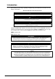
Introduction This manual provides setup, operating, troubleshooting and maintenance information for the McQuay AWS chillers. HAZARD IDENTIFICATION INFORMATION ! DANGER Dangers indicate a hazardous situation which will result in death or serious injury if not avoided. ! WARNING Warnings indicate potentially hazardous situations, which can result in property damage, severe personal injury, or death if not avoided.
Operating Limits: • Maximum standby ambient temperature, 55°C • • • Maximum operating ambient temperature is 46°C, 52°C for Premium Version Minimum operating ambient temperature (standard), 2°C Minimum operating ambient temperature (with optional low-ambient control), -18°C • Leaving chilled water temperature, 4°C to 15°C • • Leaving chilled fluid temperatures (with anti-freeze), 3°C to -8°C. Unloading is not permitted with fluid leaving temperatures below -1°C.
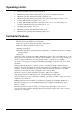
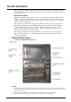
General Description The control panel is located on the front of the unit at the compressor end. There are three doors. The control panel is behind to left-hand door. The power panel is behind the middle and right-hand doors. General Description The MicroTech III control system consists of a microprocessor-based controller and a number of extension modules, which vary depending on the unit size and conformation.
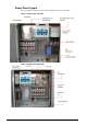
Power Panel Layout The power panel is at the front of the unit, behind the two doors to the right Figure 2, Power Panel, Left Side Figure 3, Power Panel, Right Side 6 KOMAC00607-09EN
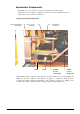
Economizer Components The chiller may or may not have economizers depending on design capacity requirements. An economizer is a well-proven device to increase a refrigerant circuit’s capacity and to a lesser extent, its efficiency. Figure 4, Economizer Components Brazed-plate Heat Exchanger Gas to Comp.
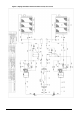
Figure 5, Piping Schematic with Economizer Circuit, One Circuit 8 KOMAC00607-09EN
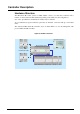
Controller Description Hardware Structure The MicroTech III control system for AWS chillers consists of a main unit controller with a number of extension I/O modules attached depending on the chiller size and configuration. One of the optional BAS communication modules may be included. An optional Remote Operator Interface panel may be included, connected with up to nine AWS units. The Advanced MicroTech III controllers used on AWS chillers are not interchangeable with previous MicroTech II controllers.
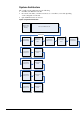
System Architecture The overall controls architecture uses the following: • One Microtech III main controller • I/O extension modules (sometimes referred to as “controllers”) as needed depending on the configuration of the unit • Optional BAS interface as selected Figure 6, System Architecture BAS Interface (Bacnet, Lon, Modbus) Microtech III Main Controller Peripheral Bus 10 I/O Extension Alarm/Limiting I/O Extension Fans Circuit 1 and 2 I/O Extension Compressor 1 I/O Extension EXV 1 I/O Extension
Sequence of Operation Figure 7, Unit Sequence of Operation (see Figure 9 for circuit sequence of operation) AWS Chiller Sequence of Operation in Cool Mode Unit power up Unit in Off state No Is unit enabled? Yes Yes The chiller may be disabled via the unit switch, the remote switch, the keypad enable setting, or the BAS network. In addition, the chiller will be disabled if all circuits are disabled, or if there is a unit alarm.
KOMAC00607-09EN
Figure 8, Circuit Sequence of Operation AWS Sequence of Operation - Circuits Unit power up When the circuit is in the Off state the EXV is closed, compressor is off, and all fans are off. Circuit is in Off state No Is circuit is enabled to start? Yes The circuit must be enabled before it can run. It may be disabled for several reasons. When the circuit switch is off, the status will be Off:Circuit Switch. If the BAS has disabled the circuit, the status will be Off:BAS Disable.
Controller Operation MicroTech III Inputs/Outputs I/O for the unit control and for circuits one and two are found on CP1. The chiller may be equipped with two or three compressors.
Extension I/O Compressor #1 to #3 Analog Inputs # X1 X2 X3 X4 X7 Description Discharge Temperature Evaporator Pressure Oil Pressure Condenser Pressure Motor Protection Signal Source NTC Thermister (10K@25°C) Ratiometric (0,5-4,5 Vdc) Ratiometric (0,5-4,5 Vdc) Ratiometric (0,5-4,5 Vdc) PTC Thermistor Expected Range -50°C – 120°C 0 to 5 Vdc 0 to 5 Vdc 0 to 5 Vdc n/a Analog Outputs # Description Not Needed Output Signal Range Signal Off Fault Fault Signal On No fault No fault Digital Inputs # X6 DI1
Extension I/O Fan Module Circuit #1 & 2 Digital Inputs # Description Output Off Output On DI1 PVM/GFP Circuit #1 Fault No fault DI2 PVM/GFP Circuit #2 Fault No fault Digital Outputs # Description Output Off Output On DO1 Circuit #1 Fan Step #5 Fan Off Fan On DO2 Circuit #1 Fan Step #6 Fan Off Fan On DO3 Circuit #2 Fan Step #5 Fan Off Fan On DO4 Circuit #2 Fan Step #6 Fan Off Fan On Extension I/O Fan Module Circuit #3 Digital Outputs # Description Output Off Output On DO1
Setpoints The following parameters are remembered during power off, are factory set to the Default value, and can be adjusted to any value in the Range column. Read and write access to these set points is determined by the Global HMI (Human Machine Interface) Standard Specification.
Description Unit Clear Ice Timer SSS Communication PVM Noise Reduction Noise Reduction Start Time Noise Reduction End Time Noise Reduction Condenser Offset BAS Protocol Ident number Baud Rate Evap LWT sensor offset Evap EWT sensor offset OAT sensor offset Compressors-Global Start-start timer Stop-start timer Pumpdown Pressure Pumpdown Time Limit Light Load Stg Dn Point Load Stg Up Point Stage Up Delay Stage Down Delay Stage Delay Clear Max # Comps Running Sequence # Cir 1 Sequence # Cir 2 Sequence # Cir 3 N
Description Unit Oil Press Differential Low Oil Level Delay High Discharge Temperat.
Auto Adjusted Ranges Some settings have different ranges of adjustment based on other settings. Cool LWT 1 and Cool LWT 2 Available Mode Selection Range Imp. Range SI Without Glycol 40 to 60oF 4 to 15 °C With Glycol 25 to 60oF -4 to 15 °C Evaporator Water Freeze Available Mode Selection Range Imp. Range SI o Without Glycol 36 to 42 F 2 to 6 °C With Glycol 0 to 42oF -18 to 6 °C Low Evaporator Pressure - Hold Available Mode Selection Range Imp.
Unit Functions Calculations LWT Slope LWT slope is calculated such that the slope represents the change in LWT over a time frame of one minute with at least five samples per minute. Pulldown Rate The slope value calculated above will be a negative value as the water temperature is dropping. For use in some control functions, the negative slope is converted to a positive value by multiplying by –1. Unit Enable Enabling and disabling the chiller is accomplished using set points and inputs to the chiller.
The Available Modes Set Point must only be changed when the unit switch is off. This is to avoid changing modes of operation inadvertently while the chiller is running. Unit Mode is set according to the following table. NOTE: An “x” indicates that the value is ignored.
Unit Status The displayed unit status is determined by the conditions in the following table: Enum 0 Status Auto 1 Off:Ice Mode Timer 2 3 4 5 6 7 Off:OAT Lockout Off:All Cir Disabled Off:Emergency Stop Off:Unit Alarm Off:Keypad Disable Off:Remote Switch 8 Off:BAS Disable 9 10 11 Off:Unit Switch Off:Test Mode Auto:Noise Reduction 12 Auto:Wait for load 13 Auto:Evap Recirc 14 Auto:Wait for flow 15 Auto:Pumpdown 16 Auto:Max Pulldown 17 Auto:Unit Cap Limit 18 Auto:Current Limit Conditions
• EWT is less than the Evap Freeze set point minus 0.6 °C and EWT sensor fault isn’t active The control state is Run when the flow switch input has been closed for a time greater than the Evaporator Recirculate set point. Pump Selection The pump output used is determined by the Evap Pump Control set point.
Leaving Water Temperature (LWT) Reset The base LWT target may be reset if the unit is in Cool mode and it is configured for a reset. The type of reset to be used is determined by the LWT Reset Type set point. When the active reset increases, the Active LWT Target is changed at a rate of 0.1 degrees F every 10 seconds. When the active reset decreases, the Active LWT Target is changed all at once. After resets are applied, the LWT target can never exceed a value of 60°F.
Outside Air Temperature (OAT) Reset The Active Leaving Water variable is reset based on the outdoor ambient temperature. Parameters used: 1. Cool LWT set point 2. Max Reset set point 3. OAT Reset is 0 if the outdoor ambient temperature is greater than Start Reset OAT set point. From Start Reset OAT set point down to Max Reset OAT the reset varies linearly from no reset to the max reset at Max Reset OAT set point.
Maximum Circuits Running If the number of compressors running is equal to the Max Circuits Running set point, no additional compressors will be started. When multiple compressors are running, one will shut down if the number of compressors running is more than the Max Circuits Running set point. Compressor Staging in Ice Mode The first compressor will start when evaporator LWT is higher than the target plus the Startup Delta T set point.
The compressor capacities are adjusted one at a time while maintaining a capacity imbalance that does not exceed 12.5%. Load/Unload Sequence This section defines which compressor is the next one to load or unload.
As the signal varies from 4 mA up to 20 mA, the maximum unit capacity changes by steps of 1% from 100% to 0%. The unit capacity is adjusted as needed to meet this limit, except that the last running compressor cannot be turned off to meet a limit lower than the minimum unit capacity. Network Limit The maximum unit capacity can be limited by a network signal. This function is only enabled if the unit control source is set to network.
Circuit Functions Calculations Refrigerant Saturated Temperature Refrigerant saturated temperature is calculated from the pressure sensor readings for each circuit. A function provides the converted value of temperature to match values published data for R134a -within 0.1 C for pressure inputs from 0 kPa to 2070kPa, -within 0.2 C for pressure inputs from -80 kPa to 0 kPa. Evaporator Approach The evaporator approach is calculated for each circuit.
• • • • • • Circuit switch is closed No circuit alarms are active Circuit Mode set point is set to Enable BAS Circuit Mode set point is set to Auto No cycle timers are active Discharge Temperature is at least 5°C higher than Oil Saturated Temperature Starting The circuit will start if all these conditions are true: • Adequate pressure in the evaporator and condenser (see No Pressure At Start Alarm) • Circuit Switch is closed • Circuit Mode set point is set to Enable • BAS Circuit Mode set point is set to
Rapid Shutdown A rapid shutdown requires the compressor to stop and the circuit to go to the Off state immediately.
Capacity will not be increased above 25% until discharge superheat has been at least 22 degrees F for a time of at least 30 seconds. Manual capacity control The capacity of the compressor can be controlled manually. Manual capacity control is enabled via a set point with choices of auto or manual. Another set point allows setting the compressor capacity from 25% to 100%. The compressor capacity is controlled to the manual capacity set point.
Condenser Fan Control The compressor must be running in order to stage fans on. All running fans will turn off when compressor goes to the off state. Saturated Condenser Temperature Target The condenser fan control logic attempts to control the saturated condenser temperature to a calculated target. A base condenser target is calculated based on evaporator saturated temperature. The equation is: Base saturated condenser target = 5/6 (saturated evaporator temperature) + 68.
When one fan is running, a fixed point is used in place of a deadband. When the Saturated Condenser temperature drops below 70°F, stage down error is accumulated. When a stage down occurs or the saturated temperature rises back within the Stage Down dead band the Stage Down Error Accumulator is reset to zero.
The target value is adjusted as needed to maintain discharge superheat within a range from 27 degrees F to 45 degrees F. As the discharge superheat approaches 27 degrees F, the suction superheat target is adjusted up. As the discharge superheat approaches 45 degrees F, the suction superheat target is adjusted down. The control will apply a 0.9 degrees F maximum reset every 5 minutes to the base target.
Alarms and Events Situations may arise that require some action from the chiller or that should be logged for future reference. A condition that requires a shutdown and/or lockout is an alarm. Alarms may cause a normal stop (with pumpdown) or a rapid stop. Most alarms require manual reset, but some reset automatically when the alarm condition is corrected. Other conditions can trigger what is known as an event, which may or may not cause the chiller to respond with a specific action in response.
2: Evaporator Pump State = Start for time greater than Recirc Timeout Set Point and all pumps have been tried Action Taken: Rapid stop all circuits Reset: This alarm can be cleared at any time manually via the keypad or via the BAS clear alarm signal. If active via trigger condition 1: When the alarm occurs due to this trigger, it can auto reset the first two times each day, with the third occurrence being manual reset.
Trigger: Sensor shorted or open Action Taken: Rapid stop all circuits Reset: This alarm can be cleared manually via the keypad, but only if the sensor is back in range. Leaving Evaporator Water Temperature Sensor Fault #1 Alarm description (as shown on screen): Evap LWT Sens#1 Fault Trigger: Sensor shorted or open Action Taken: Rapid stop of circuits 1 and 2 Reset: This alarm can be cleared manually via the keypad, but only if the sensor is back in range.
Reset: Auto reset when sensor is back in range. Unit Power Restore Event description (as shown on screen): Unit Power Restore Trigger: Unit controller is powered up. Action Taken: none Reset: none External Event Alarm description (as shown on screen): External Event Trigger: External Alarm/Event input is open for at least 5 seconds and external fault is configured as an event. Action Taken: None Reset: Auto clear when digital input is closed.
Reset: This alarm can be cleared manually if the evaporator pressure is above –10 psi. Low Pressure Start Fail Alarm description (as shown on screen): LowPressStartFail N Trigger: Circuit state = start for time greater than Startup Time set point.
Oil Level Switch Alarm description (as shown on screen): Oil Level Low N Trigger: Oil level switch open for a time greater than Oil level switch Delay while compressor is in the Run state. Action Taken: Rapid stop circuit Reset: This alarm can be cleared manually via the Unit Controller keypad.
Trigger: [Circuit 1 or Circuit 2 Number of Fans > 6 OR PVM Config = Multi Point] and communication with the I/O extension module has failed. Section 3.1 indicates the expected type of module and the address for each module. Action Taken: Rapid stop of circuit 1 and 2 Reset: This alarm can be cleared manually via the keypad when communication between main controller and the extension module is working for 5 seconds.
Reset: This alarm can be cleared manually via the keypad, but only if the sensor is back in range. Oil Pressure Sensor Fault Alarm description (as shown on screen): OilPressSensFault N Trigger: Sensor shorted or open Action Taken: Normal shutdown of circuit Reset: This alarm can be cleared manually via the keypad, but only if the sensor is back in range.
Action Taken: Action Taken: Unload the compressor by decreasing the capacity by one step every 5 seconds until the evaporator pressure rises above the Low Evaporator Pressure Unload set point. Reset: While still running, the event will be reset if evaporator pressure > (Low Evaporator Pressure Hold SP + 2psi). The event is also reset if the unit mode is switched to Ice, or the circuit is no longer in the run state.
Using the Controller The Unit Controller Operation Figure 9, Unit Controller Alarm Button Menu Button Back Button Navigation Wheel Display The keypad/display consists of a 5-line by 22 character display, three buttons (keys) and a “push and roll” navigation wheel. There is an Alarm Button, Menu (Home) Button, and a Back Button. The wheel is used to navigate between lines on a screen (page) and to increase and decrease changeable values when editing.
Or a line in a menu may be a link to further menus. This is often referred to as a jump line, meaning pushing the navigation wheel will cause a “jump” to a new menu. An arrow (>)is displayed to the far right of the line to indicate it is a “jump” line and the entire line is highlighted when the cursor is on that line. NOTE - Only menus and items that are applicable to the specific unit configuration are displayed.
previous line (up) on the page. The faster the wheel is turned the faster the cursor moves. Pushing the wheel acts as an “Enter” button. Three types of lines exist: • Menu title, displayed in the first line as in Figure 12. • Link (also called Jump) having an arrow ( > ) in the right of the line and used to link to the next menu. • Parameters with a value or adjustable setpoint. For example, “Time Until Restart” jumps from level 1 to level 2 and stops there.
Figure 13, Home Page, Main Menu Parameters and Links Home Page Enter Password Continue W/O Password Main Menu View/Set - Unit View/Set - Circuit Unit Status * Active Setpoint * Evap Leaving Water Temp * Evap Entering Water Temp * Unit Capacity * Unit Current Softload Limit Value Network Limit Value Demand Limit Value Unit Mode * Control Source * Current Limit Setpoint > > R R R R R R R R R R R/W R/W Time Until Restart Scheduled Maintenance Alarms > > > About This Chiller > View/Set Unit Status/Setti
Figure 14, Navigation, Part A View/Set Unit Status/Settings Set-Up Temperatures Date/Time/Schedules Power Conservation LON Setup BACnet IP Setup BACnet MSTP Setup Modbus Setup AWM Setup > > > > > > > > > > Design Conditions Alarm Limits > > Menu Password > View/Set Circuit > Status/Settings Compressor > > Time Until Restart Compressor 1 Cycle Time Compressor 2 Cycle Time Compressor 3 Cycle Time Compressor 4 Cycle Time Alarms Alarm Active Alarm Log Scheduled Maintenance Next Maintenance Month/Year
Figure 15, Navigation, Part B View/Set Unit Status/Settings Set-Up Temperatures Date/Time/Schedules Power Conservation LON Setup BACnet IP Setup BACnet MSTP Setup Modbus Setup AWM Setup > > > > > > > > > > Design Conditions Alarm Limits > > Menu Password > View/Set Circuit > Status/Settings Compressor > > Time Until Restart Compressor 1 Cycle Time Compressor 2 Cycle Time Compressor 3 Cycle Time Compressor 4 Cycle Time > R R R R Alarms Alarm Active Alarm Log > > > Scheduled Maintenance Next Mai
Figure 16, Navigation, Part C View/Set Unit Status/Settings Set-Up Temperatures Date/Time/Schedules Power Conservation LON Setup BACnet IP Setup BACnet MSTP Setup Modbus Setup AWM Setup > > > > > > > > > > Design Conditions Alarm Limits > > Menu Password > View/Set Circuit > Status/Settings Compressor > > Time Until Restart Compressor 1 Cycle Time Compressor 2 Cycle Time Compressor 3 Cycle Time Compressor 4 Cycle Time > R R R R Alarms Alarm Active Alarm Log > > > Scheduled Maintenance Next Mai
Optional Remote User Interface The optional remote user interface is a remote control panel that mimics operation of the controller located on the unit. Up to eight AWS units can be connected to it and selected on the screen. It provides HMI (Human Machine Interface) within a building, the building engineer’s office for example, without going outdoors to the unit. It can be ordered with the unit and shipped loose as a field installed option.
KOMAC00607-09EN
Start-up and Shutdown NOTICE McQuay service personnel or factory authorized service agency must perform initial start-up in order to activate warranty. ! CAUTION Most relays and terminals in the unit control center are powered when S1 is closed and the control circuit disconnect is on. Therefore, do not close S1 until ready for start-up or the unit may start unintentionally and possibly cause equipment damage. Seasonal Start-up 1.
! CAUTION If all power to the unit is turned off, the compressor heaters will become inoperable. Once power is resumed to the unit, the compressor and oil separator heaters must be energized a minimum of 12 hours before attempting to start the unit. Failure to do so can damage the compressors due to excessive accumulation of liquid in the compressor. Start-up After Temporary Shutdown 1.
disconnect switches to "on." This will energize the crankcase heaters. Wait a minimum of 12 hours before starting up unit. Turn compressor circuit breakers to "off" position until ready to start unit. 6. Open the optional compressor suction butterfly as well as the liquid line shutoff valves, compressor discharge valves. 7. Vent the air from the evaporator water side as well as from the system piping. Open all water flow valves and start the chilled water pump.
Field Wiring Diagram Figure 17, Typical Field Wiring Diagram, Sheet 1 NOTE: 1 Compressor Alarm No. 3 applies to future product releases. 2 The compressor alarms will not be energized by a unit fault, only the unit alarm will do so. Using the unit alarm and the circuit alarms will include all faults and also designate which compressor has an alarm. 3 Field wiring for optional BAS continued on next page.
Figure 17, Typical Field Wiring Diagram, Sheet 1 Note: The BAS interface modules and the remote display shown above are available as options.
System Maintenance General On initial start-up and periodically during operation, it will be necessary to perform certain routine service checks. Among these are checking the liquid line sight glasses, and the compressor oil level sight glass. In addition, check the MicroTech III controller temperature and pressure readings with gauges and thermometers to see that the unit has normal condensing and suction pressure and superheat and subcooling readings.
Sealing Spigot 2 3 1 2 5 • • • • 4 1 Oil Filter - 250mm 2 Oil Filter Housing Cover 3 O-Ring – 89.5x3 4 O-Ring – 76.1x3.4 5 M8 Bolts Unscrew and remove two hex head side cover bolts 180° apart. Insert M8 guide studs into the vacant holes. Remove remaining bolts, remove oil filter housing cover. Pull the oil filter off of the spigot and withdraw the oil filter from the housing and clean. Clean oil filter housing cover plate.
Remove filter and clean oil filter housing. Clean all other components. Replace the o-rings. Electrical Terminals ! DANGER Electric equipment can cause electric shock which will cause severe personal injury or death. Turn off, lock out and tag all power before continuing with following service. Panels can have more than one power source. ! CAUTION Periodically check electrical terminals for tightness and tighten as required. Always use a back-up wrench when tightening electrical terminals.
An element inside the sight glass indicates the moisture condition corresponding to a given element color. If the sight glass does not indicate a dry condition after about 12 hours of operation, the circuit should be pumped down and the filter-drier changed. An oil acid test is also recommended. Do not use the sight glass on the EXV body for refrigerant charging. Its purpose is to view the position of the valve.
Appendix Definitions Active Setpoint The active setpoint is the setting in effect at any given moment. This variation occurs on setpoints that can be altered during normal operation. Resetting the chilled water leaving temperature setpoint by one of several methods, such as return water temperature, is an example. Active Capacity Limit The active setpoint is the setting in effect at any given moment. Any one of several external inputs can limit a compressor’s capacity below its maximum value.
High Saturated Condenser – Unload Value High Cond Unload Value = Max Saturated Condenser Value – 3 degrees F This function unloads the compressor whenever the pressure approaches within 3 degrees of the maximum discharge pressure. The purpose is to keep the compressor online during periods of possibly temporary elevated pressures. Light Load Stg Dn Point The percent load point at which one of two operating compressors will shut off, transferring the unit load to the remaining compressor.
pLAN Peco Local Area Network is the proprietary name of the network connecting the control elements. Refrigerant Saturated Temperature Refrigerant saturated temperature is calculated from the pressure sensor readings for each circuit. The pressure is fitted to an R-134a temperature/pressure curve to determine the saturated temperature.
“The present publication is drawn up by of information only and does not constitute an offer binding upon McQuay. McQuay has compiled the content of this publication to the best of its knowledge. No express or implied warranty is given for the completeness, accuracy, reliability or fitness for particular purpose of its content, and the products and services presented therein. Specification are subject to change without prior notice. Refer to the data communicated at the time of the order .