
Installation manual


Installation and operation manual
5
EKCC7-W
Central control for hydroboxes
4P341705-1 – 2013.02
4.7. Control parameters
Diff. LWT Heat On/Off and Diff. LWT Cool On/Off
Defines the differential above/below which the system takes
action to switch units ON or OFF. (TempxTime counter is started,
see below).
Temperature increase slaves (Temp. Incr. slaves)
This parameter determines the increase (heating)/decrease
(cooling) for the slaves. The setpoint of the ‘leading’ unit will be
equal to the setpoint of the leaving water temperature to the
secondary circuit. The setpoint of the slaves will be the setpoint
of the leaving water temperature to the secondary circuit plus
temperature increase slaves (minus temperature increase
slaves in cooling). This will lead to fully loading up of the slave
units, and capacity control by the leading unit.
TempxTime for ON and OFF
Defines the temperature×time value that must be exceeded
before a unit is switched ON or OFF. A low value will result in
fast switching ON/OFF, a high value will result in slow switching
ON/OFF.
Start delay units (seconds)
Defines the time that must expire before the control starts the
TempxTime ON counter as explained above, after a unit has
started. Since the units need time to build up capacity, it is
advised to keep this value above 500 seconds.
Corr. CLWT sensor
This is a correction value for the common leaving water sensor.
P-heating/P-cooling
Influences the number of units to be started up at the same time
(with an interval of about 10 seconds) when heating or cooling is
started. A low value will result in more units starting up, a higher
value in less.
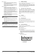
The number of units starting up when heating or cooling is
switched ON is calculated as follows:
e.g.: SP leaving water temp=50°C
Leaving water temp at startup=22°C
Number of units in system=12
P-heating=50°C
→ ((50–22)/50)*12=7 units will be started up at a time (with a
time difference of about 10 seconds)
4.8. Diagnostics
Manual operation
Change ‘Auto’ to ‘Manual’.
This allows manual ON/OFF control of the digital outputs.
(Note that during this operation, the central control itself is OFF).
Running timers
Allows readout of the actual value of the running timers set in the
control parameters.
Application info
Shows information about the installed software.
4.9. IP settings
It is possible to take over the central control over the Internet. For
this, the IP address has to be configured appropriately.
Read the actual IP from ‘Current IP settings’ and, if desired, enter a
new IP address.
Access to the central control can be achieved by going to the web
page with the configured IP. The user name is ‘ADMIN’ and the
password is ‘SBTAdmin!’ (case sensitive!).
5. Operation
5.1. Basic control
Refer to "9. Operation of the central control and menu structure" on
page 10 for basic operation of the central control.
All menu structure items are explained in detail below.
5.2. Main menu
To System info
Enters a screen with the following main information about the system.
Time and date
System mode
The system mode can be OFF, HEATING, or COOLING. If
heating or cooling is shown with a question mark, the mode is
requested, but it does not become active because the outdoor
temperature is too high. When the system is off, the letter
following OFF shows the last on mode. E.g., "OFF H" means the
system is OFF, and the last active mode was heating.
SP for LWT and Actual LWT
Setpoint and actual value of the leaving water temperature to the
secondary circuit.
Outdoor temperature
Outdoor temperature (read through Modbus from indoor unit
with Modbus address 1).
No of units ON
The number of units ON.
Backup heating
Indicates whether backup heating is ON or OFF.
To Unit info
Enters an overview screen with unit information.
The first column is the number corresponding with the Modbus
address of the unit (address set on RTD-W). The screen shows the
status (H=heating / C=cooling / DHW=domestic hot water / OFF or
error code), unit leaving water temperature (LWT), unit return water
temperature (RWT), domestic hot water temperature (DHW), and
running hours (HOURS) of the unit.
Note that the domestic hot water temperature is the temperature
detected by the domestic hot water sensor connected to the unit.
When there is an error in the unit, the corresponding error code is
shown. If ‘MDB’ (Modbus fault) is shown, check the connection to and
the status of the RTD-W.
If U5 is shown, check the P1P2 connection to the RTD-W and the
remote controller.
To view the unit’s error history, scroll to ‘STATE’ and press the Enter
button. Then select the unit number for which you want to display the
error history.
To DHW info
Available only when ‘Centralized tank’ is selected in the installer
settings. Shows the setpoint, actual domestic hot water temperature
and 3-way valve status.
NOTICE
Make sure to revert to ‘Auto’ when leaving this menu.
SP leaving water temp - leaving water temp()
P-heating
--------------------------------------------------------------------------------------------------------------------
INFORMATION
When more than one unit is connected to the same
RTD-W, a group error is shown and the LWT shown is the
average LWT of all units.