
Installation manual


Installation and operation manual
3
EKCC7-W
Central control for hydroboxes
4P341705-1 – 2013.02
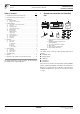
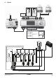
Analog inputs
- AI1-M(T7): Common leaving water sensor. This sensor
measures the leaving water temperature to the secondary
circuit. (Supplied with EKCC7-W).
- AI2-M(T7): Domestic hot water temperature. (Daikin option
EKCLWS). Only if you have a centralized tank and DHW
must be controlled by the central control.
Digital outputs
- C3-DO3(T3): Contact to start the secondary pump. This
contact closes whenever heating or cooling is ON.
- C4-DO4(T3): Contact to energize the 3-way valve for DHW.
This contact closes when DHW heating is requested.
- C5-DO5(T4): Contact to start the backup heater. This contact
closes when backup heater operation is requested.
- C8-DO8(T4): This contact closes when there is an alarm in
the system (e.g. one of the heatpump units is in alarm, faulty
common leaving water sensor, etc.).
- C9-DO9(T5): Heating operation. This contact closes when
the system is in room heating mode.
- C10-D010(T5): Cooling operation. This contact closes when
the system is in room cooling mode.
4. Installer settings
Refer to "9. Operation of the central control and menu structure" on
page 10 for basic operation of the central control.
All items in the ‘Installer settings’ menu are explained below in detail.
To make the installer settings available, scroll to ‘Installer password’
in the main menu and enter the installer password (default: ‘6000’)
and then go to the ‘Installer settings’ menu.
4.1. Confirmation of the installer settings
Some settings require a restart of the central control in order to
become effective. This is indicated in the first line of the ‘Installer
settings’ menu. When this line shows ‘Restart now?’, changes were
made in the installer settings that require a restart to become
effective. Enter the line and select to restart the central control.
When the line shows ‘No need to restart’, all changes are already
effective.
4.2. Language
Select the desired language.
4.3. Operating modes?
Define the possible operating modes of the system.
Heating only/Cooling only/Heating and cooling
This will make sure the user can only select the appropriate modes.
Restart the central control after changing these settings in order to
make them effective.
4.4. Centralized DHW tank?
Define if the system has a centralized DHW tank.
Only if the system has a centralized domestic hot water tank and field
supplied 3-way valve, select:
Centralized tank
And enter the desired value for:
DT LWT-SP tank
This value determines the temperature difference between the
setpoint of the leaving water temperature of the unit(s) and the
setpoint of the tank. The higher the value, the faster the tank can
be heated. The lower the value, the more efficiently the tank will
be heated.
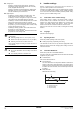
DHW differential
Differential for tank heating.
1 DHW differential
2 SP tank (set by user)
3 Start tank heating
4 Stop tank heating
INFORMATION
Contact rating:
Switching voltage AC 24 V…230 V (–20%, +10%)
Rated current (res./ind.) Max. AC 3 A / 2 A (cos φ0.6)
Switching current at AC 19 V Min. AC 30 mA
Max. external supply line fusing 6.3 A slow wire fuse or
circuit breaker.
WARNING
Do not mix SELV/PELV and line voltage on the same
terminal.
Use external protection for inductive load.
4
3
2
1