
Installation manual


EKCC7-W
Central control for hydroboxes
4P341705-1 – 2013.02
Installation and operation manual
2
2. General layout and setup of a system
The central control can control the following in a system:
Leaving water temperature to the secondary circuit (circuit to the
heat emitters)
The setpoint for the leaving water temperature to the secondary
circuit can be set. The central control will change the setpoint of
the units and switch more or less units ON/OFF in order to reach
this setpoint.
Pump of the secondary circuit
Backup heater for room heating
Domestic hot water temperature in a centralized domestic hot
water tank
In case of a system with domestic hot water, the system can be set
up in 2 ways:
1. System with integrated hot water tank(s)
In this case, the units for domestic hot water have their own
tank, 3-way valve and 3-way valve control. The parameters for
heating domestic hot water (setpoint, schedule, etc.) must be set
on the control of the unit itself. Refer to the operation/installation
manual of the unit.
On the central control, you can define whether a unit has
domestic hot water function or not. (This can be defined in the
installer settings. Refer to "Configuration" on page 4.)
If the unit is defined as a unit for domestic hot water, it will
always get the lowest priority to start up during room heating, in
order to reserve it as much as possible for DHW heating. During
room cooling, it will always get the highest priority in order to
recover the heat to the DHW tank.
Refer to Figure 3: System with integrated hot water tanks on
page 9 for a setup example.
1A~B Hydroboxes with integrated tank
3~5 Hydroboxes/inverter chillers
A Domestic hot water tanks (EKHTS200/260)
B Non-return valve (field supply)
C Backup heater (field supply)
D Leaving water temperature to secondary circuit sensor
(supplied with EKCC7-W)
E Secondary circuit pump (field supply)
F Central control (supplied with EKCC7-W)
When the system is set to heating or cooling (on the central
control or by external contact connected to the central control),
the central control will switch on the pump of the secondary
circuit and change the setpoint of the hydroboxes in order to
reach the setpoint for the leaving water temperature to the
secondary circuit. In this example, units 1A and 1B are
controlled together, since they are connected to the same
RTD-W.
If the hydroboxes cannot reach the set temperature to the
secondary circuit and depending on other parameters set on the
central control, the central control will also switch on the backup
heater.
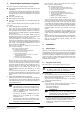
2. System with centralized domestic hot water tank
In this case, a tank sensor in the centralized tank is connected to
the central control. The central control will increase the setpoint
of the units and switch the 3-way valve when the temperature in
the tank becomes too low.
Refer to Figure 2: System with centralized domestic hot water
tank on page 8 for a setup example.
1A~5 Hydroboxes/inverter chillers
A Centralized domestic hot water tank (field supply)
B Domestic hot water sensor (Daikin option: EKCLWS)
C Non-return valve (field supply)
D 3-way valve for DHW (field supply)
E Backup heater with integrated pump (field supply)
F Leaving water temperature to secondary circuit sensor
(supplied with EKCC7-W)
G Secondary circuit pump (field supply)
H Central control (supplied with EKCC7-W)
When the system is set to heating or cooling (on the central
control or by external contact connected to the central control),
the central control will switch on the pump of the secondary
circuit, switch the hydroboxes ON/OFF and change the setpoint
in order to reach the setpoint for the leaving water temperature
to the secondary circuit. In this example, units 1A and 1B are
controlled together, since they are connected to the same
RTD-W.
If the hydroboxes cannot reach the set temperature to the
secondary circuit and depending on other parameters set on the
central control, the central control will also switch on the backup
heater.
When domestic hot water heating is required, the central control
will switch the 3-way valve for DHW and increase the setpoint of
units 1A and 1B until the required domestic hot water
temperature is reached.
3. Installation
3.1. Mounting place
When the central control is ON, the units will be controlled (setpoint
setting, ON/OFF control, etc.) by the central control. This will overrule
the ON/OFF setting on the individual remote controllers. For ON/OFF
control using the remote controllers of the units, the central control
must be set to OFF. In order to allow local control of the units at all
times, the central control must be installed in the vicinity of the
individual remote controllers.
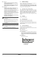
3.2. Wiring the central control
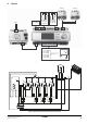
Also refer to Figure 1: Electrical wiring diagram on page 8.
Modbus wiring
The control uses Modbus to communicate with the hydroboxes.
Make sure to wire the RS485 wiring (2-wire twisted pair + shield)
from the central control to the RTD-Ws.
Also make sure to configure the addresses on the RTD-W
correctly (refer to RTD-W manual).
Digital inputs
In order to start the system in heating/cooling by an external
voltage free contact, wire the following digital inputs:
- DI1-M (T10): Heating ON
- DI2-M (T10): Cooling ON
- X1-M(T8): This voltage free input changes the value of the
outdoor temperature at which the backup heater is allowed to
operate. Also refer to "4.5. Backup heater?" on page 4.
- X2-M(T8): This voltage free input detects alarms of the
backup heater.
INFORMATION
This means that the units are put in heating mode to
heat the DHW tank. For this reason, this setup is only
applicable to EKHBRD*AC units set to configuration C
(refer to ‘Application guide Altherma Flex for
commercial applications’).
This setup is not advised for EKHVM units, since
heating mode is only possible up to an outdoor
temperature of 25°C.
For EWYQ units, post-heating of domestic hot water
might be required, since the maximum leaving water
temperature of these units is limited to 55°C.
WARNING
All electrical wiring must be installed by a licensed
electrician and must comply with local regulations.
INFORMATION
The central control can also be configured to start
heating/cooling using the central control. In that case,
it is not necessary to wire these contacts.