INSTALLATION AND OPERATION MANUAL Central control for hydroboxes EKCC7-W
EKCC7-W Table of contents Installation and operation manual Central control for hydroboxes Page 1. 1. Supplied accessories and intended use .................................... 1 Supplied accessories and intended use 2. General layout and setup of a system ....................................... 2 3. Installation ................................................................................. 2 3.1. 3.2. 1 Mounting place.............................................................................
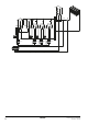
2. General layout and setup of a system Refer to Figure 2: System with centralized domestic hot water tank on page 8 for a setup example.
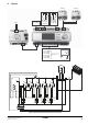
Analog inputs - AI1-M(T7): Common leaving water sensor. This sensor measures the leaving water temperature to the secondary circuit. (Supplied with EKCC7-W). - AI2-M(T7): Domestic hot water temperature. (Daikin option EKCLWS). Only if you have a centralized tank and DHW must be controlled by the central control. Digital outputs - C3-DO3(T3): Contact to start the secondary pump. This contact closes whenever heating or cooling is ON. - C4-DO4(T3): Contact to energize the 3-way valve for DHW.
4.5. Backup heater? 4.6. System layout? Define here if the system has a backup heater or not. If so, select ‘Backup heating’ and define the backup heater method. INFORMATION 3 methods for the backup heating can be defined: General note on schedule settings: Method 1: Outd Temp The backup heater will be allowed to operate, depending on the outdoor temperature. - BUH allowed: Below this temperature, BUH is allowed to operate, but BUH has the lowest priority.
4.7. Control parameters Diff. LWT Heat On/Off and Diff. LWT Cool On/Off Defines the differential above/below which the system takes action to switch units ON or OFF. (TempxTime counter is started, see below). Temperature increase slaves (Temp. Incr. slaves) This parameter determines the increase (heating)/decrease (cooling) for the slaves. The setpoint of the ‘leading’ unit will be equal to the setpoint of the leaving water temperature to the secondary circuit.
To User settings INFORMATION Opens the ‘User settings’ menu with following items: This setting may also be available on the units. Make sure the setting on the unit is equal to or higher than the setting on the central control. Time/date Enter the correct time and date if you want to use the quiet mode, room heating or DHW heating schedules. Quiet mode Select OFF, ON, or SCHEDULED. The central control will send the quiet mode command to the units as selected.
6.3. Alarm menu Press the alarm button to access the following screen: 7. Alarm list Shows a list of the current alarms. Troubleshooting MDB is shown in the ‘Unit info’ menu. Make sure that the Modbus connection to the RTD-W with the corresponding address is correct. Make sure that the correct number of connected units is defined in the installer settings. U5 is shown in the ‘Unit info’ menu. Make sure that the P1P2 connection to the RTD-W with the corresponding address is correct.
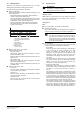
8. Figures RTD-W T7: AI1-M T7: AI2-M 230 V X1 M X2 DI1 M DI2 T8: X1-M T8: X2-M T10: DI1-M T10: DI2-M T3: C3-DO3 T3: C4-DO4 T4: C5-DO5 T4: C8-DO8 T5: C9-DO9 T5: C10-DO10 RTD-W AC 24...230 V (–20%, +10%) 0D[ $& $ $ FRV ij Min. AC 30 mA Figure 1: Electrical wiring diagram E A F D C B 1B 1A RTD-W G 3 4 RTD-W 5 RTD-W RTD-W H Figure 2: System with centralized domestic hot water tank EKCC7-W Central control for hydroboxes 4P341705-1 – 2013.
C D A A E B 3 4 5 1B 1A RTD-W RTD-W RTD-W RTD-W F Figure 3: System with integrated hot water tanks Installation and operation manual 9 EKCC7-W Central control for hydroboxes 4P341705-1 – 2013.
9. Operation of the central control and menu structure 1 2 3 4 5 1 Alarm button: press this button to enter the alarm menu. 2 Main menu button: press this button to return to the ‘MAIN MENU’ screen at all times. 3 Return button: press this button to return to the previous screen. 4 Select button: turn this button to scroll up and down through the menus. Press the button to enter your selection. 5 BSP LED. This LED should be green. See below for the possible states of the LED.
Screens shaded in gray are visible only depending on settings in the installer menu.
USER SETTINGS Time/date Quiet mode Set room mode Domestic hot water Settings SETTINGS X X X X X Quiet mode schedule X Settings for room X Settings for DHW X SETTINGS QUIET MODE SCHEDULE Monday Tuesday Wednesday Thursday Friday Saturday Sunday X X X X X X X SETTINGS FOR ROOM QUIET MODE SCHEDULE Wednesday Time 1 22:00 Time 2 08:00 Time 3 00:00 Time 4 00:00 Time 5 00:00 Time 6 00:00 1 0 0 0 0 0 SETTINGS FOR ROOM HEATING Quiet mode schedule X Room heating X Leaving water temp X Settings for
Indicates whether a restart of the central control is required to make changes made in the installer menu effective.
INSTALLER SETTINGS Restart now? Set languageh Operating modes? Centralized DHW tank? Backup heater? System layout? Control parameters Diagnostics IP settings X X X X X X X DIAGNOSTICS Manual operation Running timers Application info X X X DIAGNOSTICS Manual operation Running timers Application info X X X DIAGNOSTICS Manual operation Running timers Application info INSTALLER SETTINGS Restart now? Set languageh Operating modes? Centralized DHW tank? Backup heater? System layout? Control parameters Diag
0000000I* Copyright 2013 Daikin *4P341705-1 4P341705-1 2013.