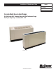
Installation & Maintenance Data IM 985-1 Group: WSHP Part Number: 669544301 Date: January 2010 Console Water Source Heat Pumps R-410A Models MHC Standard Range & MHW Geothermal Range Flat Top & Slope Top – Unit Sizes 007 – 018 Slope Top Unit Flat Top Unit ® ©2010 McQuay International
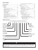
Table of Contents LonWorks Communication Module Placement . . . . . . 20 Typical Wiring Diagrams . . . . . . . . . . . . . . . . . . . . . . . . 22-23 Start-up . . . . . . . . . . . . . . . . . . . . . . . . . . . . . . . . . . . . . . . . 24 Additional Accessories (General) . . . . . . . . . . . . . . . . . . . . . 24 Thermostats . . . . . . . . . . . . . . . . . . . . . . . . . . . . . . .
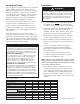
Pre-Installation Receiving and Storage Upon receipt of the equipment, check carton for visible damage. Make a notation on the shipper’s delivery ticket before signing. If there is any evidence of rough handling, immediately open the cartons to check for concealed damage. If any damage is found, notify the carrier within 48 hours to establish your claim and request their inspection and a report. The Warranty Claims Department should then be contacted.
Unit Installation (Recommended) WARNING Installation and maintenance are to be performed by qualified personnel who are familiar with local codes and Regulations, and experienced with this type of equipment. CAUTION Sharp edges can cause personal injury. Avoid contact with them. 1. Consult job blueprints for unit location. Clean area where unit is to be installed, removing all construction dirt and debris. 2.
7. Remove the filter and locate the existing 1/4" mounting holes in the bottom of the subbase labeled (5) in Figure 2 subbase detail. 11. Use a carpenters square and level to check that the unit is level and 90-degrees to the wall and floor (see letters C & D in Figure 2). 8. Be sure the subbase is tight to the wall. Transfer a mark with a marker or pencil to the floor at mounting hole locations (5). 12. The chassis back panel has a series of slots on the back flange to mount the assembly to the wall.
Alternate Unit Installation (Using Provided Brackets) Note: Use the appropriate fasteners by others in accordance with local building codes. Procedure 1. With the front, left and right cabinet panels removed, set the entire unit in its final mounting position. 2. With the chassis still mounted on the subbase, remove filter to allow access to the subbase bottom plate. 3. Locate the existing 1/4" mounting holes in the bottom of the subbase labeled (5) in Figure 3.
Piping 1. Connect units to supply and return piping in a twopipe reverse return configuration (Figure 4). A reverse return system is inherently self-balancing and requires only trim balancing where multiple quantities of units with different flow and pressure drop characteristics are connected to the same loop. A simple way to check for proper water balance is to take a differential temperature reading across the water connections when in the cooling mode.
. Units are internally trapped. Copper or PVC condensate lines can be used. A means of disconnection must be furnished to facilitate chassis removal. Shutoff/Balancing Valve Piping Each heat pump requires a shutoff valve on both the supply and return lines for easy serviceability and removal if it becomes necessary. 9. No point of the drain system may be above the drain pan of any unit. 10. Automatic flow control devices must not be installed prior to system cleaning and flushing. 11.
Optional Factory-Installed Motorized & Hand Valve Assemblies Console water source heat pumps can be configured with factory-installed motorized valves. Valves should be mounted on the return water line. All valve assemblies terminate with 1/2"-NPT threaded connections and will also accommodate factory supplied hose kits. When installing the hoses on valve assemblies, use the method as outlined in "Shutoff/Balancing Valve Piping" on page 8. Figure 7.
Motorized Isolation Valve The 2-way motorized valve kit is available as a factoryinstalled and wired option or may be ordered as a fieldinstalled accessory. Wired as shown in Figure 8, the motorized valve will open on a call for compressor operation. Valves for unit sizes 007 to 018 are 1/2". Figure 8 illustrates the wiring for a Normally Closed (NC), power open motorized valve. Figure 8.
Cleaning & Flushing Water System CAUTION Prior to first operation of any unit, the water circulating system must be cleaned and flushed of all construction dirt and debris. If the unit is provided with water shutoff valves, either electric or pressure operated, the supply and return run outs must be connected together at each unit location. This will prevent the introduction of dirt into the water circulating system. Additionally, pressure operated valves only open when the compressor is operating. 1.
Electrical Connections Note: Installation and maintenance must be performed only by qualified personnel who are familiar with local codes and regulations, and are experienced with this type of equipment. WARNING Hazardous Voltage! The installer must determine and follow all applicable codes and regulations. This equipment presents hazards of electricity, rotating parts, sharp edges, heat and weight.
Mechanical (Compressor) Heating Override to Electric Heat Operation Note: Only with units equipped with the electric heat feature In the event of a compressor failure or, electric heat is desired over mechanical (compressor) heating, a factory certified service technician may reconfigure the male and female plugs to enable electric heat. This option allows emergency electric heat when mechanical heating is not available.
Table 4. Air Limits Min. Ambient Air Normal Ambient Air Max. Ambient Air Min. Entering. Air Normal Entering Air, db/wb Max. Entering Air db/wb Standard Range Units Cooling Heating 50˚F/10˚C 50˚F/10˚C 80˚F/27˚C 70˚F/21˚C 100˚F/38˚C 85˚F/29˚C 50˚F/10˚C 50˚F/10˚C 80˚F/67˚F 70˚F 27/19˚C 21˚C 100/83˚F 80˚F 27˚C 38/28˚C Geothermal Range Units Cooling Heating 40˚F/5˚C 40˚F/5˚C 80˚F/27˚C 70˚F/21˚C 100˚F/38˚C 85˚F/29˚C 50˚F/10˚C 40˚F/5˚C 80˚F/67˚F 70˚F 27/19˚C 21˚C 100/83˚F 80˚C 38/28˚C 27˚C Table 5.
Table 8. I/O Expansion Module Configuration Jumper Settings I/O Expansion Module Jumper Description JP1 This manual covers the installation of a McQuay Console Unit - Model MHC, MHW Water Source Heat Pump.
MicroTech III Unit Controller with LonWorks® Communication Module This manual covers the installation of a McQuay Console Water Source Heat Pump. For installation and operation information on LonWorks Communication Module and other ancillary control components, see: • IM 927 - MicroTech III Unit Controller for Water Source Heat Pumps (LonWorks).
MicroTech III Controller with BACnet MS/TP Communication Module For installation and operation information on MicroTech III unit controller and other ancillary components, see: Figure 14.
MicroTech® III Unit Controller Terminals Locations and Descriptions H7 - 6 Red-Green-Yellow LED Common 24 VAC Common H8 - 1 1 Isolation Valve/Pump Request Relay N/O Fan Output - Switched L1 H8 - 2 Isolation Valve/Pump Request Relay N/C H2 - 2 Blank Terminal H8 - 3 24 VAC Common H2 - 3 Fan Neutral H9 - 1 Return Air Temperature Signal H1 - 1 24 24 VAC Power Input H1 - 2 C H2 - 1 SL1 N 1 H3 - 1 HP1-1 High Pressure Switch 1 Input Terminal 1 H9 - 2 Return Air Temperature C
Note: A random start delay time between 180 and 240 seconds is generated at power up. Location of Configuration Jumpers on the MicroTech III Unit Controller Figure 15.
Figure 16.
Typical Wiring Diagrams MicroTech III Unit Controller for Sizes 007-015 – 208/230/60Hz/1-Phase Drawing No.
Typical Wiring Diagrams MicroTech III Unit Controller With Electric Heat for Size 018 208/230/60Hz/1-Phase Drawing No.
Typical Wiring Diagrams MicroTech III Unit Controller with Communication Module and Wall-Mounted Room Temperature Sensor 265/277/60Hz/1-Phase Drawing No.
Start-up Table 10. LED Fault Indicators LEDs Indication Yellow Normal Mode Off High Pressure Fault Off Low Temperature Fault* Flash Condensate Overflow On Brownout Off Load Shed Off Unoccupied Mode On Unit Shutdown Off CAUTION Units must be checked for water leaks upon initial water system start-up. Water leaks may be a result of mishandling or damage during shipping.
Specifications–668810301 Specifications–668811201 Electrical rating: • 24 VAC (18-30 VAC) • 1 amp maximum per terminal • 3 amp maximum total load Electrical rating: • 24 VAC (18-30 VAC) • 1 amp maximum per terminal • 3 amp maximum total load Temperature control range: 45°F to 90°F (7°C to 32°C) Accuracy: ± 1°F (± 0.5°C) Temperature control range: 45°F to 90°F (7°C to 32°C) Accuracy: ± 1°F (± 0.
Programmable Electronic Thermostat (P/N 668811101) 7-Day Programmable, Auto Changeover, Fan Speed Control, Hardwired Non-Programmable Electronic Thermostat (P/N 668811001) Non-Programmable, Auto Changeover, Fan Speed Control, Hardwired • • • • • • • • • • • • • • • • • • • • • • • • 7-Day Programmable Single Stage Heat Pump/Non-Heat Pump Systems Backlit Display Single Stage Heat/Cool Systems Field Calibration Auto Changeover Button Lockout Function Two Speed Fan Control SimpleSet™ Programming Remote Tem
Wireless Temperature Control (T9000) The T9000 Wireless Temperature Control is designed to provide precision temperature control without the installation labor and expense of wiring. • Powered by AA batteries • Mounts in any suitable location that will provide good temperature control. • Large LCD display provides the user with current room temperature, set point temperature, time, program interval, and other system status information.
MicroTech III Wall-Mounted Room Temperature Sensors (Kit P/N 669529101, 669529201, 669529001) Figure 20.
Optional Remote Sensor (P/N 66720401) The fast, easy solution for temperature sensing problems. For tamper prone areas Poor airflow areas Troubled applications Foam gasket prevents drafts through wall opening • Mounts to standard 2" x 4" outlet box • 2¾"W x 4½"H • • • • 1. Remove cover from remote sensor housing. 2. Select an appropriate location for mounting the remote sensor. 3. Mount remote sensor unit using hardware provided. 4.
Outside Air Damper – Field-installed Option CAUTION To prevent infiltration of ambient conditions, it is the responsibility of the contractor to assure that factory installed gasketing matches up with the wall opening, or that additional material is used to assure a positive seal. Cold Weather Operation Console water source heat pumps may experience erratic operation during cold ambient conditions with the outside air damper in the open position.
Troubleshooting The in and outs of R-410A R-410A is a non-ozone depleting blend of two refrigerants - HFC-125 and HFC-32 in a fifty percent mixture. R-410A exhibits higher operating pressure and refrigeration capacity than R-22. R-410A is intended for use in new air conditioning applications that have traditionally used HCFC-22 (R-22). Due to higher capacity and pressure of R-410A, it must not be used in existing R-22 systems.
Troubleshooting Refrigeration Circuit Air Water Head Suction Compressor Super Temp (loops) Temp Subcooling Pressure Pressure Amp Draw Heat Symptom Differential Differential Charge Undercharge System (Possible Leak) Low Low Low High Overcharge System High High High Normal Low Air Flow Heating High High Low Air Flow Cooling Low Low Low Low Low Water Flow Heating Normal Normal High High Normal Low Low Normal Low Low Normal High Low Safety Lock Out Low Low Pressure Norm
Typical Cooling and Heating Refrigeration Cycles Figure 26. Cooling Mode Return Air Thermal Expansion Valve Coaxial Heat Exchanger Water In Coil – Air to Refrigerant Heat Exchanger Water Out Sensing Bulb and Capillary Tube Compressor Blower Reversing Valve Conditioned Air (Cooling) Cooling Refrigeration Cycle When the wall thermostat is calling for COOLING, the reversing valve directs the flow of the refrigerant, a hot gas, leaving the compressor, to the water-to-refrigerant heat exchanger.
Troubleshooting the Water Source Heat Pump Unit Figure 28. Troubleshooting Guide - Unit Operation Low voltage, check power supply voltage Fuse may be blown, circuit breaker is open Wire may be loose or broken.
Troubleshooting the MicroTech III Unit Controller Figure 29. MicroTech III Unit Controller LED Status and Faults Troubleshooting Reference DANGER Read Outputs To avoid electrical shock, personal injury or death, be sure that field wiring complies with local and national fire, safety, and electrical codes, and voltage to the system is within the limits shown in the job-specific drawings and unit electrical data plate(s).
McQuay Training and Development Now that you have made an investment in modern, efficient McQuay equipment, its care should be a high priority. For training information on all McQuay HVAC products, please visit us at www.mcquay.com and click on training, or call 540-248-9646 and ask for the Training Department. Warranty All McQuay equipment is sold pursuant to its standard terms and conditions of sale, including Limited Product Warranty. Consult your local McQuay Representative for warranty details.