
Specifications

Cat 604-3 29
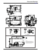
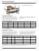
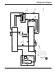
Refrigeration Diagram
Refrigeration Diagram
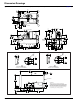
Figure 23: Refrigeration Diagram
Liquid Injection
Motor Stator Cooling
Rotor Cooling
Stepper
Motor
Valve
Controlled By
Compressor Controller
Rotor Liquid Injection
Electronic
Expansion
Valve
Controlled By Chiller
Controller
Check
Valve
Manual Shut Off Valve
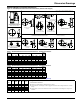
T
VFD
controller
T
Filter Dryer
Strainer
Strainer
Solenoid Valve
Controlled By
Compressor Controller
Solenoid Valve
Controlled By
Compressor Controller
Strainer
T
P
T
HPS
T
Suction
Discharge
Motor
Evaporator
Condenser
Compressor
REV 2
Feb20, 2008
Liquid
Line
T
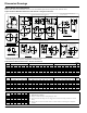
= Temperature Sensor
P
= Pressure Sensor
1
2
5
4
3
1
= Reference number
P
P
T
T
HPS
= High Pressure Switch
6
Orifice
6 Phase
configuration
shown.
3 Phase version
will have 1 heat
sink and 1
refrigerant circuit