
Specifications

28 Cat 604-3
Physical Data & Weights
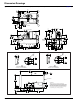
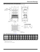
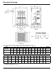
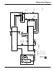
Figure 22: Lifting Points - See Installation Manual IM 1033 for handling information.
Physical Data - Evaporator
Refrigerant-side maximum working pressure is 200psig.
Water-side is 150 psi (1034 kPa) with 300 psi (2068 kPa)
available as an option. Approximate total square footage of
insulation surface required for individual packaged chillers is
tabulated by evaporator code and can be found below. The
suction elbow and compressor also require insulation. Factory-
installed insulation on cold surfaces, ¾ or 1 ½ inch thick is an
available option.
Note: Refrigerant charge will depend on a number of variables. Actual charge will be shown on the unit nameplate.
Note: Water capacity is based on standard tube configuration and standard dished heads, and may change depending on your configuration.
Consult Certified Drawing.
Physical Data - Condenser
With positive pressure systems, the pressure variance with
temperature is always predictable and the vessel design and
pressure relief protection are based upon pure refrigerant
characteristics. R-134a requires ASME vessel design,
inspection and testing and uses spring-loaded pressure relief
valves. When an over-pressure condition occurs, spring-loaded
relief valves purge only that quantity of refrigerant required to
reduce system pressure to the valve’s set pressure, and then
close.Refrigerant-side design pressure is 200 psi; Water-side
design is 150 psi with 300 psi available as an option. .
Note: Condenser pumpdown capacity based on 90% full at 90F.
Note: Water capacity based on standard configuration and standard heads, and may change depending on your configuration. Consult Certified
Drawing.
Note: See Relief Valves section of IM 1033 (available on www.daikinmcquay.com) for additional information.
Lifting Points
Lifti ng Point
Lifting Po int (Outside
Corner Hidden)
VFD Power
Panel
Power Cable Entry
Note: This drawing is for general reference only.
Refer to dimension drawings for location of components.
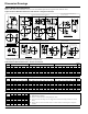
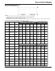
Table 11: Evaporator Physical Data
WME Model
Evaporator
Model
Tube
Length
Evaporator Water
Volume, gal (L)
Insulation Area
sq. ft. (m
2
)
Number of Relief
Valves
0500 E3012 12 ft. 147 (555) 115 (11) 1
0500 E3612 12 ft. 191 (723) 129 (12) 1
0700 E3612 12 ft. 214 (809) 129 (12) 1
Table 12: Condenser Physical Data
WMC Model
Condenser
Model
Tube
Length
Maximum Pumpdown
Capacity lb. (kg)
Water Volume
gal. (L)
Number of
Relief Valves
0500 C2612 12 ft. 1656 (751) 111 (419) 2
0500 C3012 12 ft. 2148 (975) 144 (545) 2
0700 C3012 12 ft. 2060 (934) 214 (808) 2
0700 C3612 12 ft. 2814 (1276) 337 (1276) 2