Catalog DC Inverter Single Split Models: M5LCX 010 C/CR M5LCX 015 C/CR M5LCX 020 C/CR M5LCX 025 C/CR M5LCX-2009
Table of Contents M5LCX-2009 Table of Contents Nomenclature......................................................................................................................1 Indoor Unit......................................................................................................................1 Outdoor Unit...................................................................................................................4 Product Line-Up........................................................
M5LCX-2009 Nomenclature Nomenclature Indoor Unit M 5 WM X Brand M : McQuay Refrigerant 5 : R410A Model Name WM : Wall Mounted Inverter System Type X : X series Capacity Index 010 015 020 025 : 10,000 Btu/h : 15,000 Btu/h : 20,000 Btu/h : 25,000 Btu/h Chassis G : G series Model Type “ ” R 2 : Omitted if cooling only : Heatpump 010 G R
Nomenclature M5LCX-2009 Indoor Unit M 5 CC X 010 A R Brand M : McQuay Refrigerant 5 : R410A Model Name CK CM CC : Ceiling Cassette : Ceiling Convertible : Ceiling Concealed Inverter System Type X : X series Capacity Index 010 015 020 025 : 10,000 Btu/h : 15,000 Btu/h : 20,000 Btu/h : 25,000 Btu/h Chassis A C E : A series : C series : E series Model Type “ ” R : Omitted if cooling only : Heatpump 3
M5LCX-2009 Nomenclature Outdoor Unit M 5 LC X 010 Brand M : McQuay Refrigerant 5 : R410A Model Name LC : Single Split Condensing Unit Inverter System Type X : X series Capacity Index 010 015 020 025 : 10,000 Btu/h : 15,000 Btu/h : 20,000 Btu/h : 25,000 Btu/h Chassis C : C series Model Type “ ” R 4 : Omitted if cooling only : Heatpump C R
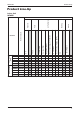
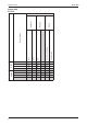
Product Line-Up M5LCX-2009 Product Line-Up Indoor Unit M5WMX CE Auto Restart Others Saranet Filter ACITE ACITE ACITE ACITE X X X X X X X X X X X X X X X X X X X X X X X X 010GR 015GR 020GR 025GR ACITE ACITE ACITE ACITE X X X X X X X X X X X X X X X X X X X X X X X X O2 Therapy Ionizer Filter Non-Thermal Plasma (NTP) Marking Air Purification VA2.
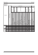
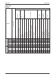
COOLING ONLY 020A 025A AFAA AFAA X X HEAT PUMP 020AR 025AR AFAA AFAA X X 6 Saranet Filter Ionizer Filter X X X X X X X X X X X X X X X X Auto Restart with Cape Tube CE Non-Thermal Plasma (NTP) O2 Therapy Nano Technology Air Filtration Negative Ionizer with Auto Air Swing X X w/o Cape Tube X X 090A-EC 090A-AP G11(w/o Turbo Mode) G17 M5CKX Nomenclature Others Refrigerant Control Marking Air Purification PCB Handset Product Line-Up M5LCX-2009 Indoor Unit M5CKX-A Classification
COOLING ONLY 010C 015C 020C AFAA AFAA AFAA X X X HEAT PUMP 010CR 015CR 020CR AFAA AFAA AFAA X X X Saranet Filter Ionizer Filter X X X X X X X X X X X X X X X X X X X X X X Auto Restart with Cape Tube CE Non-Thermal Plasma (NTP) O2 Therapy Nano Technology Air Filtration Negative Ionizer with Auto Air Swing X X X w/o Cape Tube X X X 090A-EC 090A-AP G7(w/o Turbo Mode) G17 M5CKX Nomenclature Others Refrigerant Control Marking Air Purification PCB Handset M5LCX-2009 Product Line-Up I
M5LCX-2009 Product Line-Up Indoor Unit PLCKX X X PLCKXC-G17 X X X PLCKXCR-G17 X X X COOLING ONLY HEAT PUMP 8 Auto Restart with Auto Air Swing X G18 PLCKXA-G17 G17 CE Nomenclature Others Marking Handset Classification
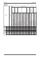
G17 015E ACHVA X X X X X X 020E ACHVA X X X X X X 025E ACHVA X X X X X X 015ER ACGVA X X X X X X 020ER ACGVA X X X X X X 025ER ACGVA X X X X X X Auto Restart with Auto Air Swing w/o Cap Tube with Cap Tube CE Non-Thermal Plasma (NTP) O2 Therapy Saranet Filter Ionizer Filter 09A-EC 09A-AP G17 (w/o Turbo Mode) M5CMX Nomenclature Nano Technology Air Filtration COOLING ONLY Negative Ionizer HEATPUMP Others Refrigerant Control Marking Air Purification PCB Handset M5LCX-2009 Product L
10 G17 010C AFAA X X X X X X 015C AFAA X X X X X X 020C AFAA X X X X X X 025C AFAA X X X X X X 010CR AFAA X X X X X X 015CR AFAA X X X X X X 020CR AFAA X X X X X X 025CR AFAA X X X X X X Auto Restart with Cap Tube CE Non-Thermal Plasma (NTP) O2 Therapy Nano Technology Air Filtration Negative Ionizer Saranet Filter Ionizer Filter 09A-EC 09A-AP Nomenclature M5CCX SLM WIRED with EPS Drain Pan COOLING ONLY w/o Cap Tube HEATPUMP Others Refrigerant Control Marking Air Purific
M5LCX-2009 Product Line-up Outdoor Unit M5LCX X X X X X X X X ACOTA 015CR ACOUA ACITA X X X X X X 020CR ACOTA X X 025CR ACOTA X X 025C Others Marking Compressor Safety Devices DC Inverter Scroll DC Inverter Rotary X X X X X X X X X X X X X X X LP X X X X X X X X X X X X X X X X X HP X X X X X Contactor X X X X X X X X X X Bare X X X X X X X X X X Blue coated Drain Elbow ACITA ACIUA 010CR ACOTA ACOUA 020C Gold coated EXV X X X X X X 015C Fin Refrigerant Co
Features M5LCX-2009 Features Self Diagnosis The microprocessor provides the possibility to detect and diagnose any fault or malfunction that occurs in the system. The error will be reflected by the blinking of the LED lights. Advance Technology Incorporating fuzzy logic control enables greater flexibility in system control handling to achieve • Powerful, efficient and economical operation. • Even room temperature control. • Constant and quiet compressor operation.
M5LCX-2009 Application Information Application Information Operating Range Ensure the operating temperature is in allowable range. Cooling Only Outdoor temp. (°C DB) 46 ! 35 The use of your air conditioner outside the range of working temperature and humidity can result in serious failure. STD 19 15 Caution : 24 Indoor temp. (°C WB) Heatpump Heating Cooling 6 Outdoor temp. (°C DB) Outdoor temp. (°C WB) 18 STD 46 35 STD 19 -9 15 21 27 Indoor temp. (°C WB) 15 24 Indoor temp.
Application Information Refrigerant Circuit Diagram Model: M5LCX010C/CR-M5WMX010G/GR M5LCX015C/CR-M5WMX015G/GR Model: M5LCX020C/CR-M5WMX020G/GR M5LCX025C/CR-M5WMX025G/GR 14 M5LCX-2009
M5LCX-2009 Application Information Model: M5LCX020C/CR-M5CKX020A/AR M5LCX025C/CR-M5CKX025A/AR M5LCX025C/CR-M5CKX020C/CR Model: M5LCX010C-M5CKX010C M5LCX015C-M5CKX015C 15
Application Information Model: M5LCX020C-M5CMX020E M5LCX025C-M5CMX025E Model: M5LCX020CR-M5CMX020ER M5LCX025CR-M5CMX025ER 16 M5LCX-2009
M5LCX-2009 Application Information Model: M5LCX020C-M5CMX020E M5LCX025C-M5CMX025E Model: M5LCX010C-M5CCX010C M5LCX015C-M5CCX015C 17
Application Information Model: M5LCX020CR-M5CCX020CR M5LCX025CR-M5CCX025CR Model: M5LCX010CR-M5CCX010CR M5LCX015CR-M5CCX015CR 18 M5LCX-2009
M5LCX-2009 Application Information Controller G17 1 2 P1 P2 10 9 3 4 SLEEP 7 CANCEL 5 SET OFF TIMER 13 SET ON TIMER 14 8 MODE 12 CANCEL 6 11 15 Operation Guide 1 Transmission Source • The source where the signal will be transmitted. 2 Signal Transmission Indication • Blink to confirm that the last setting has been transmitted to the unit. 3 Temperature Setting • To set the desired room temperature, press the or button to increase orde crease the set temperature.
Application Information M5LCX-2009 SLM 3 1 Temperature (Seven Segments) 7 • To indicate the ambient temperature set by the user. 2 3 8 Auto Selection 9 Fan and Ventilation Mode • Press the fan button to set the desired selection. 6 Operation Selection Mode • Press the mode button to select the type of operation mode. • Cooling unit: COOL, DRY, FAN. • Heat pump unit: AUTO, COOL, DRY, FAN, HEAT. “Sleep” Function • Press the sleep button to select the sleep function.
Application Information M5LCX-2009 Installation Guideline Safety Precautions CAUTION WARNING • Installation and maintenance should be performed by qualified persons who are familiar with local code and regulation, and experienced with this type of appliance. • All field wiring must be installed in accordance with the national wiring regulation. • Ensure that the rated voltage of the unit corresponds to that of the name plate before commencing wiring work according to the wiring diagram.
Application Information Installation Diagram 22 M5LCX-2009
Application Information M5LCX-2009 Location and Space Indoor Unit Wall Mounted Install the fan coil (indoor) unit at a location with the following requirements • Location is suitable for wiring, piping and drainage. • No obstruction of air flow into and out of unit where cooler air can be evenly distributed.(See fig. 1) • Ensure that air discharge is not short circuited with air intake. • Ensure that wall is sufficiently strong, rigid, flat, perpendicular and vibration free.
M5LCX-2009 Application Information CAUTION : • If the condensing unit is operated in an atmosphere containing oils (including machine oils), salt (coastal area), sulphide gas (near hot spring, oil refinery plant), such substances may lead to failure of the unit. • If there is any obstacle higher than 2m, or if there is any obstruction at the upper part of the unit, please allow more space than the figure indicated in the above table.
M5LCX-2009 Application Information Indoor Unit Preparation • The refrigerant piping can be routed to the unit in 5 directions, by using the cut outs in the unit casing. 3 2 1 4 5 • Carefully bend the pipes to the required position to align with the hole. For right hand and rear side draw out, hold the bottom of the piping and fix direction before shaping it to the desired position. The condensation drain hose should be taped to the pipes with vinyl tape.
M5LCX-2009 Application Information Indoor Unit Ceiling Cassette Min 0.5 m Min 0.5 m Max 3.0 m Max 3.0 m Min 1.0 m Beam Preliminary Site Survey • Electrical supply and installation is to confirm to local authority’s (e.g. National Electrical Board) codes and regulations. • Voltage supply fluctuation must not exceed ± 10% of rated voltage. Electricity supply lines must be independent of welding transformers which can cause high supply fluctuation.
M5LCX-2009 Application Information Unit Hanging Indo or U nit Ceiling Board M5CKX-A/C 35.0mm (MCK-A) 30.0mm (MCK-C) • • • • Confirm the pitch of the hanging rod is 790.0mm X 620.5mm (M5CKX-A) Hold the unit and hand it on the hanging rod with the nut and washer. Adjust the unit height to 35.0mm between the indoor unit bottom surface and the ceiling surface. Confirm with a level gauge that the unit is installed horizontally and tighten the nut and bol to prevent unit falling and vibration.
Application Information M5LCX-2009 Panel Installation • The front panel can only be fitted in one direction, follow the piping direction. (Follow piping arrow sticker on the front panel). • Be sure to remove the installation template before installing the front panel. • Open the air intake grille by pulling back the catchers and remove it together with filter from panel. • Install the front frame panel onto the indoor unit by using 4 screws and tighten it completely to prevent cool air leakage.
Application Information M5LCX-2009 Short Duct Specification Application for M5CKX-A Series only • The indoor unit is provided with air discharge and air intake “knock-out” hole for duct connection. However the connection of the short duct for air discharge is possible on only one side. • The use of short duct for air discharge will improve air flow distribution if there is an obstruction (such as alighting fixture) or in a long, narrow room or an L-shaped room.
M5LCX-2009 Application Information Fresh Air Intake For M5CKX-C Unit Take off the panel from the indoor unit Remove the PE foam from the drain pan and another one on the unit. Remove the pre-punched panel on the CKC unit with a screwdriver. The diameter of the air intake knock out hole is 65mm. Then, fix the fresh air kit (refer to parts list) to the hole. Finally, a flexible duct is connected to let the fresh air moving in. Fig. 2 The direction of the fresh air intake is shown as fig. 2.
M5LCX-2009 Application Information Indoor Unit Ceiling Convertible Preliminary Site Survey • Electrical supply and installation is to confirm to local authority's (e.g. National Electrical Board) codes and regulations. • Voltage supply fluctuation must not exceed ± 10% of rated voltage. Electricity supply lines must be independent of welding transformers which can cause high supply fluctuation. • Ensure that the location is convenient for wiring, piping and drainage.
M5LCX-2009 Application Information Please ensure that the following steps are taken: • Check the gradient for drainage flow as recommended in Figure H. • Provide clearance for easy servicing and optimal air flow as shown in Figure I. • The indoor unit must be installed such that there is no short circuit of the cool discharge air with the warm return air. • Don not install the indoor unit where there is direct sunlight shining on the unit.
M5LCX-2009 Application Information Under Ceiling Installation Install the Suspension Bolts 1. Install the suspension bolts so that it can support the indoor unit. 2. Adjust the distance to ceiling before installation. 3. Refer to the dimension given (Fig. 5) to install the unit. Install the Indoor Unit 1. Insert the suspension bolts into the fittings of the hanger bracket. 2. Set the nuts and washer on the both side of the metal fittings. 3. Secure it with nuts. 4.
Application Information M5LCX-2009 Floor Standing Installation 1. Refer to the dimension as illustrated when installing the mounting bracket. 2. Determine the pipe hose position using the rear piping hole. Drill the pipe hole at the slight downward slant to the outdoor side.
Application Information M5LCX-2009 Piping and Drain Hose Installation Under Ceiling Type 1. The piping direction can be 2 ways as illustrated. 2. The drain hose is only 1 way. OR Floor Standing Type OR How to Install the Drain Hose 1. Remove the 2 screws and the drain pipe holder. 2. Cut a slit for the drain hose hole. 3. Place the drain hose on the v-shape area and secure it with drain pipe holder and 2 screws.
Application Information How to Remove the Air Inlet Grille M5LCX-2009 1. Remove the air inlet grille by both hands as the direction shown. 2. Loosen the screws for fixing the panel arm (3 screws – Left, Right and Center). Do not remove the screws at this time. 3. Move the air inlet grille upward, and then turn it backwards. (Do not use too much force). 4. Remove the grille holder (both left and right side). After that, remove the air intake grille. 5. Remove the grille holder (center) from the panel.
Application Information M5LCX-2009 How to Install the Air Filter To Adjust the Vane Direction Adjust the vane linkage as the direction shown to get the required vane direction. 70.0 Dimension of the Fresh Air Intake Hole 64.0 70.0 3.
Application Information M5LCX-2009 Indoor Unit Ceiling Concealed Preliminary Survey • Electrical supply and installation is to confirm to local authority’s (e.g. National Electrical Board) codes and regulations. • Voltage supply fluctuation must not exceed ± 10% of rated voltage. Electricity supply lines must be independent of welding transformers which can cause high supply fluctuation. • Ensure that the location is convenient for wiring, piping and drainage.
M5LCX-2009 Application Information Outdoor Unit As condensing temperature rises, evaporating temperature rises and cooling capacity drops. In order to achieve maximum cooling capacity, the location selected for outdoor unit should fulfill the following requirements: • Install the condensing (outdoor) unit in such a way that hot air distributed by the outdoor condensing unit cannot be drawn in again (as in the case of short circuit of hot discharge air).
M5LCX-2009 Application Information Installation Clearances • Outdoor units must be installed such that there is no short circuit of the hot discharge air or obstruction to smooth air flow. Select the coolest possible place where intake air should not be hotter than the outside temperature. A Dimension Minimum distance mm/in 40 B A 300/11.8 B 500/19.
M5LCX-2009 Application Information Condensed Water Disposal Of Outdoor Unit (Heat Pump Unit Only) • There are 2 holes on the base of Outdoor Unit for condensed water to flow out. Insert the drain elbow to one of the holes. • To install the drain elbow, first insert one portion of the hook to the base (portion A), then pull the drain elbow in the direction shown by the arrow while inserting the other portion to the base. After the installation, check to ensure that the drain elbow clings to base firmly.
M5LCX-2009 Application Information Wiring Important: The figures shown in the table are for information purpose only. They should be checked and selected to comply with the local/national codes of regulations. This is also subject to the type of installation and conductors used. Model M5LCX010/015C/CR Voltage range M5LCX020/025C/CR 220V-240V / 1 Ph / 50Hz + Power supply cable size (mm2) Number of wire 1.5 3 2.5 3 Interconnection cable size (mm2) Number of wire 1.5 3 2.
Application Information M5LCX-2009 Refrigerant Piping A) A maximum pipe length and maximum number of bends Always choose the shortest path for refrigerant piping and follow the recommendation as tabulated below: Model M5LCX010C/CR M5LCX015C/CR M5LCX020C/CR M5LCX025C/CR Maximum length, L (m/ft) 15/49 15/49 30/98 30/98 Max. elevation, H (m/ft) 5/16.4 5/16.4 8/26.2 8/26.2 Max.
Application Information M5LCX-2009 • The exact length of pipe protruding from the face of the flare die is determined by the flaring tool. The table shows the use of an imperial die and rigid die. 6.35 / 1/4” 9.52 / 3/8” 12.70 / 1/2” 15.88 / 5/8” 19.05 / 3/4” A (mm) Imperial 1.3 1.6 1.9 2.2 2.5 Rigid 0.7 1.0 1.3 1.7 2.0 Copper tube Swaging block D A Pipe Ø, D (mm/in) Fix the pipe firmly on the flare die.
M5LCX-2009 Application Information Special Precautions for R410A Special Precautions When Dealing With Refrigerant R410A Unit (1) What is new refrigerant R410A? R410A is a new HFC refrigerant which does not damage the ozone layer. The working pressure of this new refrigerant is 1.6 times higher than conventional refrigerant (R22), thus proper installation / servicing is essential.
Application Information M5LCX-2009 (d) When charging R410A, ensure that only liquid is being withdrawn from the cylinder or can. This is to ensure that only the original composition of R410A is being delivered into the system. The liquid composition can be different from the vapor composition. Dip-pipe Invert cylinder without dip-pipe Liquid withdrawal (e) Normally, the R410A cylinder or can is being equipped with a dip pipe for liquid withdrawal.
Application Information M5LCX-2009 Liquid side Indoor Unit Discharge Valve Outdoor Unit Close Gas side Open Vacuum pump Low Suction valve Hi Close Close Additional Charge Per Meter Model M5LCX010/015/020/025C/CR R410A 19.5 g/m The additional refrigerant charge amount recommended is a guideline for long piping application.
M5LCX-2009 Engineering and Physical Data Engineering and Physical Data General Data - Cooling Only MODEL OUTDOOR UNIT INDOOR UNIT NOMINAL CAPACITY NOMINAL TOTAL INPUT POWER NOMINAL RUNNING CURRENT POWER SOURCE EER 9000 W 2638 3517 W 780 1095 A 3.80 5.40 220 - 240 / 1 / 50 220 - 240 / 1 / 50 W/W 3.40 3.21 l/s / CFM 142 / 300 156 / 330 l/s / CFM 118 / 250 123 / 260 LOW l/s / CFM 94 / 200 99 / 210 dBA 38 / 35 / 30 39 / 36 / 31 HEIGHT mm/in 260 / 10.2 260 / 10.
Engineering and Physical Data M5LCX-2009 General Data - Cooling Only MODEL OUTDOOR UNIT M5LCX020C M5LCX025C INDOOR UNIT M5WMX020G M5WMX025G Btu/h 18000 21000 W 5275 6155 NOMINAL TOTAL INPUT POWER W 1632 1991 NOMINAL RUNNING CURRENT A 7.90 11.
M5LCX-2009 Engineering and Physical Data General Data - Cooling Only (With Torque Control) MODEL OUTDOOR UNIT M5LCX015C M5WMX010G M5WMX015G Btu/h 9000 12000 W 2784 3517 1100 INDOOR UNIT NOMINAL CAPACITY M5LCX010C NOMINAL TOTAL INPUT POWER W 820 NOMINAL RUNNING CURRENT A 3.80 5.
Engineering and Physical Data M5LCX-2009 General Data - Heat pump MODEL OUTDOOR UNIT M5LCX010CR M5LCX015CR INDOOR UNIT M5WMX010GR M5WMX015GR 9000 12000 Btu/h NOMINAL COOLING CAPACITY NOMINAL HEATING CAPACITY W 2638 3517 Btu/h 11500 14000 W 3370 4103 NOMINAL TOTAL INPUT POWER (COOLING) W 780 1095 NOMINAL TOTAL INPUT POWER (HEATING) W 980 1270 NOMINAL RUNNING CURRENT (COOLING) A 3.80 5.40 NOMINAL RUNNING CURRENT (HEATING) A 4.80 6.
Engineering and Physical Data M5LCX-2009 General Data - Heat pump MODEL OUTDOOR UNIT M5LCX020CR M5LCX025CR INDOOR UNIT M5WMX020GR M5WMX025GR Btu/h 18000 W 5275 6155 Btu/h 19000 22000 W 5568 6448 NOMINAL TOTAL INPUT POWER (COOLING) W 1632 1991 NOMINAL TOTAL INPUT POWER (HEATING) W 1631 2013 NOMINAL RUNNING CURRENT (COOLING) A 7.90 11.30 NOMINAL COOLING CAPACITY NOMINAL HEATING CAPACITY NOMINAL RUNNING CURRENT (HEATING) 21000 A 8.00 11.
M5LCX-2009 Engineering and Physical Data General Data - Heat pump (With Torque Control) MODEL OUTDOOR UNIT M5LCX010CR M5LCX015CR INDOOR UNIT M5WMX010GR M5WMX015GR NOMINAL COOLING CAPACITY NOMINAL HEATING CAPACITY Btu/h 9500 W 2638 3517 Btu/h 11500 13000 12000 W 3370 3810 NOMINAL TOTAL INPUT POWER (COOLING) W 820 1100 NOMINAL TOTAL INPUT POWER (HEATING) W 930 1057 NOMINAL RUNNING CURRENT (COOLING) A 3.80 5.40 NOMINAL RUNNING CURRENT (HEATING) A 4.50 5.
M5LCX-2009 Engineering and Physical Data General Data - Cooling only MODEL OUTDOOR UNIT M5LCX020C M5LCX025C INDOOR UNIT M5CKX020A M5CKX025A NOMINAL CAPACITY NOMINAL TOTAL INPUT POWER NOMINAL RUNNING CURRENT POWER SOURCE EER Btu/h 18000 W 5275 6155 W 1694 2054 A 7.46 9.
M5LCX-2009 Engineering and Physical Data General Data - Cooling only MODEL OUTDOOR UNIT M5LCX010C M5LCX015C INDOOR UNIT M5CKX010C M5CKX015C NOMINAL CAPACITY Btu/h 9500 12000 W 2784 3517 1116 NOMINAL TOTAL INPUT POWER W 833 NOMINAL RUNNING CURRENT A 3.95 5.
M5LCX-2009 Engineering and Physical Data General Data - Cooling only MODEL OUTDOOR UNIT M5LCX020C INDOOR UNIT M5CKX020C NOMINAL CAPACITY NOMINAL TOTAL INPUT POWER NOMINAL RUNNING CURRENT POWER SOURCE EER Btu/h 18000 W 5275 W 1646 A 7.23 V/Ph/Hz 230 / 1 / 50 W/W REFRIGERANT TYPE REFRIGERANT CONTROL (EXPANSION DEVICE) CONTROL INDOOR UNIT AIR FLOW PACKING DIMENSION l/s / CFM 212 / 450 MEDIUM l/s / CFM 203 / 430 LOW l/s / CFM 194 / 410 dBA 47 / 46 / 44 HEIGHT mm/in 250 / 9.
Engineering and Physical Data M5LCX-2009 General Data - Heat pump MODEL OUTDOOR UNIT INDOOR UNIT M5LCX020CR M5LCX025CR M5CKX020AR M5CKX025AR Btu/h 18000 21000 W 5275 6155 Btu/h 19000 22000 W 5568 6448 NOMINAL TOTAL INPUT POWER (COOLING) W 1694 2054 NOMINAL COOLING CAPACITY NOMINAL HEATING CAPACITY NOMINAL TOTAL INPUT POWER (HEATING) W 1693 2076 NOMINAL RUNNING CURRENT (COOLING) A 7.46 9.05 NOMINAL RUNNING CURRENT (HEATING) A 7.45 9.
Engineering and Physical Data M5LCX-2009 General Data - Heat pump MODEL OUTDOOR UNIT M5LCX010CR M5LCX015CR INDOOR UNIT M5CKX010CR M5CKX015CR Btu/h NOMINAL COOLING CAPACITY NOMINAL HEATING CAPACITY 9500 12000 W 2784 3517 Btu/h 11500 13000 W 3370 3810 NOMINAL TOTAL INPUT POWER (COOLING) W 833 1116 NOMINAL TOTAL INPUT POWER (HEATING) W 943 1073 NOMINAL RUNNING CURRENT (COOLING) A 3.95 5.37 NOMINAL RUNNING CURRENT (HEATING) A 4.55 5.
M5LCX-2009 Engineering and Physical Data General Data - Heat pump MODEL OUTDOOR UNIT M5LCX020CR INDOOR UNIT M5CKX020CR Btu/h NOMINAL COOLING CAPACITY 18000 W 5275 Btu/h 19000 W 5668 NOMINAL TOTAL INPUT POWER (COOLING) W 1646 NOMINAL TOTAL INPUT POWER (HEATING) W 1645 NOMINAL RUNNING CURRENT (COOLING) A 7.23 NOMINAL HEATING CAPACITY NOMINAL RUNNING CURRENT (HEATING) A 7.22 V/Ph/Hz 230 / 1 / 50 EER W/W 3.
Engineering and Physical Data M5LCX-2009 General Data - Cooling Only MODEL OUTDOOR UNIT INDOOR UNIT NOMINAL CAPACITY NOMINAL TOTAL INPUT POWER NOMINAL RUNNING CURRENT POWER SOURCE EER INDOOR UNIT PACKING DIMENSION 12000 3520 3520 W 1130 1135 A 5.50 5.40 V/Ph/Hz 220 - 240 / 1 / 50 220 - 240 / 1 / 50 W/W 3.21 3.
Engineering and Physical Data M5LCX-2009 General Data - Cooling Only MODEL OUTDOOR UNIT M5LCX020C M5LCX025C INDOOR UNIT M5CMX020E M5CKX025E NOMINAL CAPACITY Btu/h 18000 21000 W 5280 6155 NOMINAL TOTAL INPUT POWER W 1663 2025 NOMINAL RUNNING CURRENT A 7.34 8.93 V/Ph/Hz 220 - 240 / 1 / 50 220 - 240 / 1 / 50 W/W 3.15 3.
Engineering and Physical Data M5LCX-2009 General Data - Heat pump MODEL OUTDOOR UNIT M5LCX015CR M5LCX015CR * INDOOR UNIT M5CMX015ER M5CMX015ER * Btu/h 12000 12000 W 3520 3520 Btu/h 14000 13000 W 4100 3810 NOMINAL TOTAL INPUT POWER (COOLING) W 1130 1135 NOMINAL TOTAL INPUT POWER (HEATING) W 1305 1092 NOMINAL RUNNING CURRENT (COOLING) A 5.50 5.40 NOMINAL RUNNING CURRENT (HEATING) A 6.40 5.10 V/Ph/Hz 220 - 240 / 1 / 50 220 - 240 / 1 / 50 EER W/W 3.21 3.
Engineering and Physical Data M5LCX-2009 General Data - Heat pump MODEL OUTDOOR UNIT INDOOR UNIT M5LCX020CR M5LCX025CR M5CMX020ER M5CMX025ER Btu/h 18000 21000 W 5275 6155 Btu/h 19000 22000 W 5568 6448 NOMINAL TOTAL INPUT POWER (COOLING) W 1663 2025 NOMINAL TOTAL INPUT POWER (HEATING) W 1662 2047 NOMINAL RUNNING CURRENT (COOLING) A 7.30 8.89 NOMINAL RUNNING CURRENT (HEATING) A 7.30 9.
Engineering and Physical Data M5LCX-2009 General Data - Cooling Only MODEL OUTDOOR UNIT M5LCX010C M5LCX015C INDOOR UNIT M5CCX010C M5CCX015C NOMINAL CAPACITY Btu/h 9500 12000 W 2784 3517 NOMINAL TOTAL INPUT POWER W 830 1136 NOMINAL RUNNING CURRENT A 3.98 5.54 V/Ph/Hz 220 - 240 / 1 / 50 220 - 240 / 1 / 50 W/W 3.35 3.
Engineering and Physical Data M5LCX-2009 General Data - Cooling Only MODEL OUTDOOR UNIT M5LCX020C M5LCX025C INDOOR UNIT M5CCX020C M5CCX025C NOMINAL CAPACITY NOMINAL TOTAL INPUT POWER NOMINAL RUNNING CURRENT POWER SOURCE EER Btu/h 18000 W 5275 6155 W 1683 2045 A 7.55 9.11 V/Ph/Hz 220 - 240 / 1 / 50 220 - 240 / 1 / 50 W/W 3.13 3.
Engineering and Physical Data M5LCX-2009 General Data - Heat pump MODEL OUTDOOR UNIT M5LCX010CR M5LCX015CR INDOOR UNIT M5CCX010CR M5CCX015CR NOMINAL COOLING CAPACITY NOMINAL HEATING CAPACITY Btu/h 9500 W 2784 3517 Btu/h 11500 13000 12000 W 3370 3810 NOMINAL TOTAL INPUT POWER (COOLING) W 830 1136 NOMINAL TOTAL INPUT POWER (HEATING) W 940 1093 NOMINAL RUNNING CURRENT (COOLING) A 3.98 5.54 NOMINAL RUNNING CURRENT (HEATING) A 4.58 5.
Engineering and Physical Data M5LCX-2009 General Data - Heat pump MODEL OUTDOOR UNIT M5LCX020CR M5LCX025CR INDOOR UNIT M5CCX020CR M5CCX025CR Btu/h NOMINAL COOLING CAPACITY NOMINAL HEATING CAPACITY 18000 21000 W 5275 6155 Btu/h 19000 22000 W 5568 6448 NOMINAL TOTAL INPUT POWER (COOLING) W 1683 2045 NOMINAL TOTAL INPUT POWER (HEATING) W 1682 2067 NOMINAL RUNNING CURRENT (COOLING) A 7.55 9.11 NOMINAL RUNNING CURRENT (HEATING) A 7.54 9.
Engineering and Physical Data M5LCX-2009 Components Data - Cooling Only MODEL OUTDOOR UNIT M5LCX010C M5LCX015C INDOOR UNIT M5WMX010G M5WMX015G TYPE INDOOR FAN INDOOR FAN MOTOR CROSS FLOW FAN 1 1 MATERIAL ACRYLO NITRILE STYRENE ACRYLO NITRILE STYRENE DIRECT DIRECT DRIVE DIAMETER mm/in 97 / 3.8 97 / 3.8 LENGTH mm/in 718 / 28.2 718 / 28.
Engineering and Physical Data M5LCX-2009 Components Data - Cooling Only MODEL OUTDOOR UNIT M5LCX020C M5LCX025C INDOOR UNIT M5WMX020G M5WMX025G TYPE INDOOR FAN INDOOR FAN MOTOR CROSS FLOW FAN 1 1 MATERIAL ACRYLO NITRILE STYRENE ACRYLO NITRILE STYRENE DRIVE DIAMETER mm/in LENGTH mm/in TYPE QUANTITY INDEX OF PROTECTION (IP) TYPE OUTDOOR FAN 810 / 32.9 810 / 32.
Engineering and Physical Data M5LCX-2009 Components Data - Cooling Only (with Torque Control) MODEL OUTDOOR UNIT M5LCX010C M5LCX015C INDOOR UNIT M5WMX010G M5WMX015G TYPE INDOOR FAN INDOOR FAN MOTOR CROSS FLOW FAN 1 1 MATERIAL ACRYLO NITRILE STYRENE ACRYLO NITRILE STYRENE DIRECT DIRECT DRIVE DIAMETER mm/in 97 / 3.8 97 / 3.8 LENGTH mm/in 718 / 28.2 718 / 28.
Engineering and Physical Data M5LCX-2009 Components Data - Heat pump MODEL OUTDOOR UNIT M5LCX010CR M5LCX015CR INDOOR UNIT M5WMX010GR M5WMX015GR TYPE INDOOR FAN INDOOR FAN MOTOR CROSS FLOW FAN 1 1 MATERIAL ACRYLO NITRILE STYRENE ACRYLO NITRILE STYRENE DIRECT DIRECT DRIVE DIAMETER mm/in 97 / 3.8 97 / 3.8 LENGTH mm/in 718 / 28.2 718 / 28.
Engineering and Physical Data M5LCX-2009 Components Data - Heat pump MODEL OUTDOOR UNIT M5LCX020CR M5WMX020GR INDOOR UNIT TYPE INDOOR FAN INDOOR FAN MOTOR 1 1 MATERIAL ACRYLO NITRILE STYRENE ACRYLO NITRILE STYRENE DRIVE DIAMETER mm/in LENGTH mm/in TYPE QUANTITY INDEX OF PROTECTION (IP) MATERIAL DIAMETER mm/in TYPE QUANTITY INDEX OF PROTECTION (IP) TYPE OIL TYPE OIL AMOUNT 3 cm / fl.oz.
Engineering and Physical Data M5LCX-2009 Components Data - Heat pump (with Torque Control) MODEL OUTDOOR UNIT M5LCX010CR M5LCX015CR INDOOR UNIT M5WMX010GR M5WMX015GR TYPE INDOOR FAN INDOOR FAN MOTOR CROSS FLOW FAN 1 1 MATERIAL ACRYLO NITRILE STYRENE ACRYLO NITRILE STYRENE DIRECT DIRECT DRIVE DIAMETER mm/in 97 / 3.8 97 / 3.8 LENGTH mm/in 718 / 28.2 718 / 28.
Engineering and Physical Data M5LCX-2009 Components Data - Cooling only MODEL OUTDOOR UNIT M5LCX020C M5LCX025C INDOOR UNIT M5CKX020A M5CKX025A TYPE INDOOR FAN INDOOR FAN MOTOR TURBO FAN 1 1 MATERIAL ASG20 ASG20 DRIVE DIAMETER mm/in LENGTH mm/in TYPE QUANTITY INDEX OF PROTECTION (IP) TYPE QUANTITY OUTDOOR FAN MATERIAL DIAMETER mm/in TYPE QUANTITY INDEX OF PROTECTION (IP) TYPE COMPRESSOR OIL TYPE 3 OIL AMOUNT cm / fl.oz.
Engineering and Physical Data M5LCX-2009 Components Data - Cooling only MODEL OUTDOOR UNIT M5LCX010C M5LCX015C INDOOR UNIT M5CKX010C M5CKX015C TYPE QUANTITY INDOOR FAN INDOOR FAN MOTOR ASG20 ASG20 DIRECT DIRECT 330 / 13.0 DIAMETER mm/in 330 / 13.0 LENGTH mm/in 178 / 7.0 178 / 7.
Engineering and Physical Data M5LCX-2009 Components Data - Cooling only MODEL OUTDOOR UNIT M5LCX020C INDOOR UNIT M5CKX020C TYPE INDOOR FAN INDOOR FAN MOTOR TURBO FAN QUANTITY 1 MATERIAL ASG20 DRIVE DIRECT DIAMETER mm/in 330 / 13.0 LENGTH mm/in 178 / 7.
M5LCX-2009 Engineering and Physical Data Components Data - Heat pump MODEL OUTDOOR UNIT M5LCX020CR M5LCX025CR INDOOR UNIT M5CKX020AR M5CKX025AR TURBO FAN TURBO FAN 1 1 TYPE QUANTITY INDOOR FAN INDOOR FAN MOTOR MATERIAL ASG20 ASG20 DRIVE DIRECT DIRECT 450 / 17.7 DIAMETER mm/in 450 / 17.7 LENGTH mm/in 170 / 6.7 170 / 6.
Engineering and Physical Data M5LCX-2009 Components Data - Heat pump MODEL OUTDOOR UNIT M5LCX010CR M5LCX015CR INDOOR UNIT M5CKX010CR M5CKX015CR TURBO FAN TURBO FAN TYPE INDOOR FAN INDOOR FAN MOTOR QUANTITY 1 1 MATERIAL ASG20 ASG20 DRIVE DIRECT DIRECT 330 / 13.0 DIAMETER mm/in 330 / 13.0 LENGTH mm/in 178 / 7.0 178 / 7.
Engineering and Physical Data M5LCX-2009 Components Data - Heat pump MODEL OUTDOOR UNIT M5LCX020CR INDOOR UNIT M5CKX020CR TYPE INDOOR FAN INDOOR FAN MOTOR TURBO FAN QUANTITY 1 MATERIAL ASG20 DRIVE DIRECT DIAMETER mm/in LENGTH mm/in TYPE QUANTITY 1 INDEX OF PROTECTION (IP) PROPELLER QUANTITY 1 MATERIAL GLASS REINFORCED ACRYL STYRENE RESIN DRIVE DIRECT DIAMETER OUTDOOR FAN MOTOR mm/in TYPE QUANTITY 1 INDEX OF PROTECTION (IP) IP54 DC INVERTER SCROLL OIL TYPE RB68A / FREOL
Engineering and Physical Data M5LCX-2009 Components Data - Cooling only MODEL OUTDOOR UNIT M5LCX015C M5LCX015C * INDOOR UNIT M5CMX015E M5CMX015E * TYPE INDOOR FAN INDOOR FAN MOTOR CROSS FLOW FAN 2 2 MATERIAL ABS ABS DRIVE DIAMETER mm/in LENGTH mm/in TYPE QUANTITY INDEX OF PROTECTION (IP) TYPE QUANTITY OUTDOOR FAN MATERIAL DRIVE DIAMETER OUTDOOR FAN MOTOR mm/in TYPE QUANTITY INDEX OF PROTECTION (IP) TYPE COMPRESSOR OIL TYPE 3 OIL AMOUNT cm / fl.oz.
Engineering and Physical Data M5LCX-2009 Components Data - Cooling Only MODEL OUTDOOR UNIT M5LCX020C M5LCX025C INDOOR UNIT M5CMX020E M5CMX025E TYPE INDOOR FAN INDOOR FAN MOTOR CROSS FLOW FAN 2 2 MATERIAL ABS ABS DIRECT DIRECT 146 / 5.8 DRIVE DIAMETER mm/in 146 / 5.8 LENGTH mm/in 200 / 7.9 200 / 7.
Engineering and Physical Data M5LCX-2009 Components Data - Heat pump MODEL OUTDOOR UNIT M5LCX015CR M5LCX015CR * INDOOR UNIT M5CMX015ER M5CMX015ER * TYPE INDOOR FAN INDOOR FAN MOTOR CROSS FLOW FAN 2 2 MATERIAL ABS ABS DRIVE DIAMETER mm/in LENGTH mm/in 200 / 7.
Engineering and Physical Data M5LCX-2009 Components Data - Heat pump MODEL OUTDOOR UNIT M5LCX020CR M5LCX025CR INDOOR UNIT M5CMX020ER M5CMX025ER TYPE INDOOR FAN INDOOR FAN MOTOR CROSS FLOW FAN 2 2 MATERIAL ABS ABS DRIVE DIAMETER mm/in LENGTH mm/in 200 / 7.
Engineering and Physical Data M5LCX-2009 Components Data - Cooling only MODEL OUTDOOR UNIT M5LCX010C M5LCX015C INDOOR UNIT M5CCX010C M5CCX015C TYPE INDOOR FAN INDOOR FAN MOTOR BLOWER WHEEL 1 2 MATERIAL GALVANISED STEEL GALVANISED STEEL DRIVE DIAMETER mm/in LENGTH mm/in TYPE QUANTITY INDEX OF PROTECTION (IP) TYPE QUANTITY OUTDOOR FAN MATERIAL DRIVE DIAMETER OUTDOOR FAN MOTOR mm/in TYPE QUANTITY INDEX OF PROTECTION (IP) TYPE COMPRESSOR OIL TYPE 3 OIL AMOUNT cm / fl.oz.
Engineering and Physical Data M5LCX-2009 Components Data - Cooling only MODEL OUTDOOR UNIT M5LCX020C M5LCX025C INDOOR UNIT M5CCX020C M5CCX025C TYPE INDOOR FAN INDOOR FAN MOTOR BLOWER WHEEL BLOWER WHEEL QUANTITY 2 2 MATERIAL GALVANISED STEEL GALVANISED STEEL DRIVE DIAMETER mm/in LENGTH mm/in 202 / 8.
Engineering and Physical Data M5LCX-2009 Components Data - Heat pump MODEL OUTDOOR UNIT M5LCX010CR M5LCX015CR INDOOR UNIT M5CCX010CR M5CCX015CR TYPE INDOOR FAN INDOOR FAN MOTOR BLOWER WHEEL 1 2 MATERIAL GALVANISED STEEL GALVANISED STEEL DRIVE DIAMETER mm/in LENGTH mm/in 202 / 8.
Engineering and Physical Data M5LCX-2009 Components Data - Heat pump MODEL OUTDOOR UNIT M5LCX020CR M5LCX025CR INDOOR UNIT M5CCX020CR M5CCX025CR TYPE INDOOR FAN INDOOR FAN MOTOR BLOWER WHEEL 2 2 MATERIAL GALVANISED STEEL GALVANISED STEEL DRIVE DIAMETER mm/in LENGTH mm/in 202 / 8.
Outline and Dimension M5LCX-2009 Outline and Dimension Outdoor Unit Model: M5LCX010/015C/CR Note: Dimension in mm 70014056769 Outdoor Unit Model: M5LCX020/025C/CR MODEL M5LCX020C/CR M5LCX025C/CR A 855 855 B 628 730 C D E 328 508 181 328 513 182 F 44 44 G 93 93 H I 149 101 149 101 70014056769 88 J 113 113 K 603 603 L 126 126 M 164 164 N 17 17 O 49 47 P 32 32 Q 3 3 R 23 23 S 73 73 T 75 75 Note: Dimension in mm
Outline and Dimension M5LCX-2009 Indoor Unit Model: M5WMX010/015G/GR Note: Dimension in mm Indoor Unit Model: M5WMX020/025G/GR MODEL A M5WMX 020/025G/GR 1062 B C D E 304 220 912 294 F G H I J 99 51 8 48 43 K L M N O 354 403 160 138 160 Note: Dimension in mm 89
Outline and Dimension M5LCX-2009 Indoor Unit Model: M5CKX020/025A/AR, M5CKX010/015/020C/CR MODEL A B C D E F G H I J 820 820 378 350 28 930 930 626 626 555 (32,3) (32,3) (14,9) (13.7) (1,1) (36.6) (36.
Outline and Dimension M5LCX-2009 Indoor Unit Model: M5CCX010/015/020/025C/CR MODEL A M5CCX010C/CR 31 (1,2) 741 702 662 10 765 72 261 411 351 225 211 232 212,8 114 (29,2) (27,6) (26,1) (0,4) (30,1) (2,8) (10,3) (16,2) (13,8) (8,9) (8,3) (9,1) (8,4) (4,5) M5CCX015C/CR 31 (1,2) 881 842 802 10 905 72 261 411 351 225 211 232 212,8 114 (34,7) (33,1) (31,6) (0,4) (35,6) (2,8) (10,3) (16,2) (13,8) (8,9) (8,3) (9,1) (8,4) (4,5) M5CCX020C/CR 31 (1,2) 1041 1002 962 10 1065 72 261 411 351 225 211 232 212,8
M5LCX-2009 Electrical Data Electrical Data Electrical Data - Cooling Only MODEL OUTDOOR UNIT M5LCX010C M5LCX015C INDOOR UNIT M5WMX010G M5WMX015G INSULATION GRADE POWER SOURCE INDOOR MOTOR V/Ph/Hz CLASS E 220 - 240 / 1 / 50 RATED INPUT POWER W 38 40 RATED RUNNING CURRENT A 0.19 0.20 MOTOR OUTPUT W 17 17 4 4 POLES INSULATION GRADE POWER SOURCE OUTDOOR MOTOR RATED INPUT POWER V/Ph/Hz CLASS B CLASS B 220 - 240 / 1 / 50 220 - 240 / 1 / 50 W 56 71 RATED RUNNING CURRENT A 0.
Electrical Data M5LCX-2009 Electrical Data - Cooling Only (With Torque Control) MODEL OUTDOOR UNIT M5LCX010C M5LCX015C INDOOR UNIT M5WMX010G M5WMX015G INSULATION GRADE POWER SOURCE INDOOR MOTOR CLASS E 220 - 240 / 1 / 50 V/Ph/Hz 220 - 240 / 1 / 50 RATED INPUT POWER W 38 40 RATED RUNNING CURRENT A 0.19 0.
M5LCX-2009 Electrical Data Electrical Data - Cooling Only MODEL OUTDOOR UNIT M5LCX020C M5LCX025C INDOOR UNIT M5WMX020G M5WMX025G INSULATION GRADE POWER SOURCE INDOOR MOTOR CLASS E CLASS E V/Ph/Hz 220 - 240 / 1 / 50 220 - 240 / 1 / 50 RATED INPUT POWER W 60 76 RATED RUNNING CURRENT A 0.31 0.40 MOTOR OUTPUT W 40 40 POLES 4 4 CLASS E CLASS E V/Ph/Hz 220 - 240 / 1 / 50 220 - 240 / 1 / 50 W 130 140 RATED RUNNING CURRENT A 0.58 0.
Electrical Data M5LCX-2009 Electrical Data - Cooling Only MODEL OUTDOOR UNIT M5LCX020C M5LCX025C INDOOR UNIT M5CKX020A M5CKX025A INSULATION GRADE POWER SOURCE INDOOR MOTOR V/Ph/Hz CLASS E 220 - 240 / 1 / 50 RATED INPUT POWER W 122 138 RATED RUNNING CURRENT A 0.53 0.61 MOTOR OUTPUT W 35 45 POLES 6 6 CLASS B CLASS B V/Ph/Hz 220 - 240 / 1 / 50 220 - 240 / 1 / 50 W 130 170 RATED RUNNING CURRENT A 0.58 0.
M5LCX-2009 Electrical Data Electrical Data - Cooling Only MODEL OUTDOOR UNIT M5LCX010C M5LCX015C INDOOR UNIT M5CKX010C M5CKX015C INSULATION GRADE CLASS E CLASS E V/Ph/Hz 220 - 240 / 1 / 50 220 - 240 / 1 / 50 RATED INPUT POWER W 54 60 RATED RUNNING CURRENT A 0.23 0.27 MOTOR OUTPUT W 16 18 POWER SOURCE INDOOR MOTOR POLES 6 6 CLASS B CLASS B V/Ph/Hz 220 - 240 / 1 / 50 220 - 240 / 1 / 50 W 56 71 RATED RUNNING CURRENT A 0.24 0.
Electrical Data M5LCX-2009 Electrical Data - Cooling Only MODEL OUTDOOR UNIT M5LCX020C INDOOR UNIT M5CKX020C INSULATION GRADE INDOOR MOTOR CLASS E V/Ph/Hz 220 - 240 / 1 / 50 RATED INPUT POWER W 68 RATED RUNNING CURRENT A 0.30 MOTOR OUTPUT W 22 POWER SOURCE POLES 6 INSULATION GRADE POWER SOURCE OUTDOOR MOTOR RATED INPUT POWER CLASS B V/Ph/Hz 130 RATED RUNNING CURRENT A 0.
M5LCX-2009 Electrical Data Electrical Data - Cooling Only MODEL OUTDOOR UNIT M5LCX015C M5CMX015E INDOOR UNIT INSULATION GRADE POWER SOURCE INDOOR MOTOR CLASS B V/Ph/Hz RATED INPUT POWER W 79 RATED RUNNING CURRENT A 0.34 MOTOR OUTPUT W 26 POLES 4 INSULATION GRADE POWER SOURCE OUTDOOR MOTOR CLASS B V/Ph/Hz 220 - 240 / 1 / 50 RATED INPUT POWER W 71 RATED RUNNING CURRENT A 0.
Electrical Data M5LCX-2009 Electrical Data - Cooling Only (With Torque Control) MODEL OUTDOOR UNIT M5LCX015C INDOOR UNIT M5CMX015E INSULATION GRADE POWER SOURCE INDOOR MOTOR CLASS B V/Ph/Hz W 79 RATED RUNNING CURRENT A 0.34 MOTOR OUTPUT W 26 POLES 4 INSULATION GRADE POWER SOURCE OUTDOOR MOTOR CLASS B V/Ph/Hz 220 - 240 / 1 / 50 RATED INPUT POWER W 71 RATED RUNNING CURRENT A 0.
M5LCX-2009 Electrical Data Electrical Data - Cooling Only MODEL OUTDOOR UNIT INDOOR UNIT INSULATION GRADE CLASS E CLASS E 220 - 240 / 1 / 50 220 - 240 / 1 / 50 RATED INPUT POWER W 101 109 RATED RUNNING CURRENT A 0.46 0.49 MOTOR OUTPUT W 50 65 POLES INSULATION GRADE POWER SOURCE OUTDOOR MOTOR RATED INPUT POWER V/Ph/Hz 4 4 CLASS B CLASS B 220 - 240 / 1 / 50 220 - 240 / 1 / 50 W 130 170 RATED RUNNING CURRENT A 0.58 0.
Electrical Data M5LCX-2009 Electrical Data - Cooling Only MODEL OUTDOOR UNIT M5LCX010C M5LCX015C INDOOR UNIT M5CCX010C M5CCX015C INSULATION GRADE CLASS E CLASS E V/Ph/Hz 220 - 240 / 1 / 50 220 - 240 / 1 / 50 W 65 96 RATED RUNNING CURRENT A 0.29 0.42 MOTOR OUTPUT W 30 50 POWER SOURCE INDOOR MOTOR RATED INPUT POWER POLES 4 4 CLASS B CLASS B V/Ph/Hz 220 - 240 / 1 / 50 220 - 240 / 1 / 50 W 56 71 RATED RUNNING CURRENT A 0.24 0.
M5LCX-2009 Electrical Data Electrical Data - Cooling Only MODEL OUTDOOR UNIT M5LCX020C M5LCX025C INDOOR UNIT M5CMX020C M5CMX025C INSULATION GRADE POWER SOURCE INDOOR MOTOR V/Ph/Hz CLASS E 220 - 240 / 1 / 50 RATED INPUT POWER W 135 152 RATED RUNNING CURRENT A 0.60 0.67 MOTOR OUTPUT W 80 100 4 4 CLASS B 220 - 240 / 1 / 50 CLASS B 220 - 240 / 1 / 50 POLES INSULATION GRADE POWER SOURCE OUTDOOR MOTOR RATED INPUT POWER V/Ph/Hz W 130 140 RATED RUNNING CURRENT A 0.58 0.
M5LCX-2009 Wiring Diagram Wiring Diagram Outdoor Unit Model: M5LCX010/015C/CR Indoor Unit Model: M5WMX010/015G/GR 103
Wiring Diagram Outdoor Unit Model: M5LCX020/025C/CR 104 M5LCX-2009 Indoor Unit Model: M5WMX020/025G/GR
M5LCX-2009 Outdoor Unit Model: M5LCX020/025C/CR Wiring Diagram Indoor Unit Model: M5CKX020/025A/AR 105
M5LCX-2009 Wiring Diagram Outdoor Unit Model: M5LCX010/015C/CR 106 Indoor Unit Model: M5CKX010/015C/CR
Wiring Diagram M5LCX-2009 Outdoor Unit Model: M5LCX020C/CR Indoor Unit Model: M5CKX020C/CR 107
M5LCX-2009 Wiring Diagram Outdoor Unit Model: M5LCX015C/CR 108 Indoor Unit Model: M5CMX015E/ER
M5LCX-2009 Outdoor Unit Model: M5LCX020/025C/CR Wiring Diagram Indoor Unit Model: M5CMX020/025E/ER 109
M5LCX-2009 Wiring Diagram Outdoor Unit Model: M5LCX010/015C/CR 110 Indoor Unit Model: M5CCX010/015C/CR
M5LCX-2009 Outdoor Unit Model: M5LCX020/025C/CR Wiring Diagram Indoor Unit Model: M5CCX020/025C/CR 111
M5LCX-2009 Servicing And Maintenance Servicing And Maintenance Caution • Disconnect from the main power supply before servicing the air conditioner unit. • DO NOT pull out the power cord when the power is ON. This may cause serious electrical shocks which may result in fire hazards. Service Parts Maintenance Procedures Period Indoor Air Filters 1.Remove any dust adhering to the filter by using a vacuum cleaner or wash in lukewarm water (below 40ºC/104ºF) with a neutral cleaning detergent. 2.
Troubleshooting M5LCX-2009 Troubleshooting When a malfunction of the air conditioner unit is detected, immediately switch off the main power supply before proceeding with the following troubleshooting procedures. The following are common fault conditions and simple troubleshooting tips. If any other fault conditions which are not listed occur, contact your nearest local dealer. DO NOT attempt to troubleshoot the unit by yourself.
M5LCX-2009 Troubleshooting Diagnostic Guidelines By means of pressure reading: Probable cause Too high A little high Normal Circuit A little low Data Too low Pressure High side Low side 1. 2. 3. 4. High side Low side 1. Poor compression / no compression (compressor defective) 2. Reversing valve leaking. High side Low side 1. 2. 3. 4. 5. 6. Undercharged with refrigerant. Refrigerant leakage. Air filter clogged / dirty (indoor unit). Indoor fan locked / seized.
Troubleshooting M5LCX-2009 By means of diagnostic flow chart: Generally, there are two kinds of problems, i.e. starting failure and insufficient cooling. “Starting failure” is caused by electrical defect while improper application or defects in refrigerant circuit causes “Insufficient cooling ”.
M5LCX-2009 Troubleshooting ii ) Diagnosis of Refrigerant Circuit / Application There might be some causes where the unit starts running but does not perform satisfactorily, i.e. insufficient cooling. Judgement could be made by measuring temperature difference of indoor unit’s intake and discharge air as well as running current. : Faulty : Check : Cause ................................................
Troubleshooting M5LCX-2009 Insufficient Heating Restricted Air Circulation High Heating Load Refrigerant Circuit Compressor Indoor/Outdoor Coil Dirty (Clogged) .................................................. Clean The Coil Indoor Air Filter Dirty ................................................ Clean The Filter Fan Motor Malfunction ........................... Change Or Repair The Motor Obstruction At Air Inlet/Outlet Of Indoor/Outdoor Unit ................................
M5LCX-2009 Troubleshooting Indicator Lights IR Signal Receiver When an infrared remote control operating signal has been transmitted, the signal receiver on indoor unit will made a (beep) sound to comfirm acceptance of the signal transmission. The table shows the LED indicator lights for the indoor air conditioner unit under normal operation and fault conditions. The LED indicator lights are located at the middle of the air conditioner unit for 5WMX-G/GR serires.
Troubleshooting M5LCX-2009 Compressor Stopped Troubleshooting Instructions (Applicable to Inverter System Only) Keep the Main Power Supply ON Open up the Outdoor Unit’s Top Panel or Service Panel DO NOT TOUCH ANY OF THE WIRES INSIDE THE UNIT! Notice the Yellow LED on the P.C.
M5LCX-2009 Exploded View And Parts List Exploded View And Parts List INDOOR UNIT MODEL : M5WMX010/015G/GR 16 13 No Description 1 2 3 4 5 6 7 8 9 10 Assy. Chassis Motor, Blower Blower Bush, Fan Assy. Heat Exchanger M5WMX - 010G/GR M5WMX - 015G/GR Piping Clamp Assy. Drain Pan Drain Hose Assy. Control Box Cover Assy.
Exploded View And Parts List M5LCX-2009 INDOOR UNIT MODEL : M5WMX020/025G/GR 18 14 17 No Description Part Number No Description Part Number 1 2 3 4 5 6 7 8 9 10 R50124068170 R50034074747 R03029029158 R11014023775 R50024072203 R12014071297 R50124068171 R10024015319 R50124074814 11 12 13 R50124074743 R50124071426 Assy. Chassis Motor, Blower Blower Bush, Fan Assy. Heat Exchanger Piping Clamp Assy. Drain Pan Drain Hose Assy. Control Box Cover Assy.
Exploded View And Parts List INDOOR UNIT MODEL : M5CKX020/025A/AR 122 M5LCX-2009
Exploded View And Parts List M5LCX-2009 MODEL : M5CKX020/025A/AR No Description 1 2 3 4 5 6 7 8 9 10 11 12 13 14 15 16 Assy. Base Pan Motor, Fan M5CKX - 020A M5CKX - 020AR M5CKX - 025A M5CKX - 025AR Bush, Fan Motor Turbo Fan Assy. Heat Exchanger M5CKX - 020A M5CKX - 020AR M5CKX - 025A M5CKX - 025AR Support Bracket Pump, Water Bush, Drain Pump Drain Hose Switch, Water Level Support, Coil Assy. Partition Front Side Panel Valve Plate Drain Connector Assy.
Exploded View And Parts List INDOOR UNIT MODEL : M5CKX010/015/020C/CR 124 M5LCX-2009
Exploded View And Parts List M5LCX-2009 MODEL : M5CKX010/015/020C/CR No Description 1 2 3 4 5 6 7 8 9 10 Assy. Base Pan Assy. Casing Side A Panel Side B Panel Assy.
Exploded View And Parts List INDOOR UNIT MODEL : M5CMX015/020/025E/ER 126 M5LCX-2009
Exploded View And Parts List M5LCX-2009 MODEL : M5CMX015/020/025E/ER No Description 1 2 3 4 5 6 7 8 Assy. Top Panel Assy. Heat Exchanger M5CMX - 015E/ER M5CMX - 020E/ER M5CMX - 025E/ER Assy. Vane Assy. Drain Pan M5CMX - 015/020/025E M5CMX - 015/020/025ER Assy.
M5LCX-2009 Exploded View And Parts List INDOOR UNIT MODEL : M5CCX010C/CR No Description 1 2 3 4 5 6 7 Part Number Cabinet Assy. Fan Deck Assy. Heat Exchanger Assy. Drain Pan Assy. Secondary Drain Pan Hanger Control Module R01013034004 R50014032627 R50024079383 R50063033907 R50015035045 R01014032372 M5CCX - 010C M5CCX - 010CR R04084100996 R04084101005 No Description 8 Assy.
M5LCX-2009 Exploded View And Parts List INDOOR UNIT MODEL : M5CCX015/020/025C/CR 129
M5LCX-2009 Exploded View And Parts List MODEL : M5CCX015/020/025C/CR No Description 1 2 3 4 5 6 Cabinet M5CCX - 015C/CR M5CCX - 020C/CR M5CCX - 025C/CR Assy. Fan Deck M5CCX - 015C/CR M5CCX - 020C/CR M5CCX - 025C/CR Assy. Heat Exchanger M5CCX - 015C/CR M5CCX - 020C/CR M5CCX - 025C/CR Assy. Drain Pan M5CCX - 015C/CR M5CCX - 020C/CR M5CCX - 025C/CR Assy.
Exploded View And Parts List M5LCX-2009 OUTDOOR UNIT MODEL : M5LCX010/015C/CR No Description Part Number No Description Assy. Base Pan Assy. Outdoor Coil M5LCX - 010C M5LCX - 015C Assy. Outer Coil M5LCX - 010CR M5LCX - 015CR 3 Compressor 4 Valve Bracket 5 Assy. Rev. Valve 4 Ways 6 Assy.
M5LCX-2009 Exploded View And Parts List OUTDOOR UNIT MODEL : M5LCX020/025C/CR No Description 1 2 3 4 5 6 7 8 9 10 Assy. Base Pan Assy. Outdoor Coil Compressor Assy. Valve Bracket M5LCX - 020C/CR M5LCX - 025C/CR Assy. Rev. Valve 4 Ways Assy.
Products manufactured in an ISO certified facility. This document contains the most current product information as of this printing. For the most up-to-date product information, please go to www.mcquay.com. © 2009 McQuay International +1 (800) 432-1342 www.mcquay.