MWMX - 2005 DC Inverter Wall Mounted Models: MWMX 010FR MWMX 015FR REGISTERED ISO 9002 ©2004 McQuay International +1 (800) 432-1342 www.mcquay.
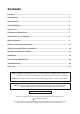
Contents Features ........................................................................................................................ 1 Nomenclature ............................................................................................................... 2 Specifications ............................................................................................................... 3 Operating Range ...................................................................................................
Features • Energy Saving Total energy saved can be as high as 30% compared to the conventionally controlled units. • Efficient McQuay DC Inverter series achieve excellent efficient with high EER & COP rating. • Comfortable Users enjoy better comfort and quietness with inverter technology.
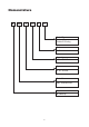
Nomenclature M WM X 010 F R Model Type R : heatpump Omitted if Cooling Series F : F series Capacity 010 : 10,000 Btu/h System X : DC Inverter Model Name WM : Wall Mounted Brand M : McQuay 2
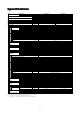
Specif ica tions Specifica ications MODEL INDOOR UNIT OUTDOOR UNIT NOMINAL COOLING CAPACITY NOMINAL HEATING CAPACITY COIL INDOOR UNIT TUBE FIN COIL PIPE OUTDOOR UNIT FAN COMP.
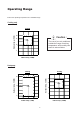
Operating Range Ensure the operating temperature is in allowable range. Cooling only Outdoor temp. (°CDB) Cooling 46 Caution : 35 STD The use of your air conditioner outside the range of working temperature and humidity can result in serious failure. 19 0 24 15 Indoor temp. (°CWB) Heatpump Cooling Heating 6 Outdoor temp. (°CDB) Outdoor temp. (°CWB) 18 STD 46 35 STD 19 0 -9 15 21 27 15 24 Indoor temp. (°CWB) Indoor temp.
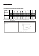
Noise Le vel Lev Sound Pressure Level (Measured In Anechoic Room) DC Inverter Wall Mounted Unit Model MWMX 010FR MWMX 015FR 1/1 Octave Sound Pressure Level (dB, ref 20µPa) Speed Overall Noise (RPM) 125 Hz 250 Hz 500 Hz 1 kHz 2 kHz 4 kHz 8 kHz A (dBA) Criteria H (1250) 32 33 35 34 31 23 16 38 33 M (1110) 32 29 32 31 27 18 14 35 30 L (980) 29 26 29 26 21 15 12 30 24 H (1300) 32 34 36 36 32 24 16 39 35 M (1150) 32 30 33 33 29 20 15 36 32 L (1000)
MMWX 010FR NC CURVE Measured in anechoic room at 1m front and 0.8m below the vertical centre line of the unit MMWX 015FR NC CURVE Measured in anechoic room at 1m front and 0.
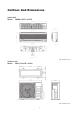
Outlines And Dimensions Indoor Unit Model : MWMX 010FR / 015FR Note : Dimension in mm Outdoor Unit Model : M5LCX 010CR / 015CR Note : Dimension in mm 7
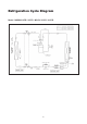
Refrigeration Cycle Diagram Model : MWMX 010FR / 015FR - M5LCX 010CR / 015CR 8
Wiring Diagrams Model : MWMX 010FR / 015FR Model : M5LCX 010CR / 015CR 9
Remote Controller Operation Guide G7 Remote Controller 1 2 Transmission source • The source where the signal will be transmitted Signal transmission indication • Blink to confirm the last setting has been send to the unit. 4 Temperature setting • To set the desired • • 3 room temperature, press the button to increase or decrease the set temperature. The temperature setting range is from 16°C to 30°C (Optional setting 18°C to 30°C).
INDICATOR LIGHTS IR signal receiver Inverted Cooling Unit When all infrared remote control operating signal has been transmitted, the signal receiver on indoor unit will make a (beep) sound to confirm acceptance of the transmitted signal. The table shows the LED indicator lights for the air conditioner unit under normal operation and fault conditions. The LED indicator lights are located at the bottom right side of the air conditioner unit.
Inverter Heatpump Unit LED Indicator Lights For Inverter Heatpump Unit Cool / Dry Heat Stand-by / Fan Timer LED Display The LED in indoor and outdoor unit indicate operation modes / faults detected Normal Operation / Fault Condition Cool / Dry Heat Stand by Action Timer / Cooling mode - / Dry mode - Stand-by / Fan mode - - ON / Heat mode - / Auto mode - Defrost operation - / Compressor overload protection Call your dealer Indoor temperature senso
Compressor Stopped Special Instruction Keep the main power supply ON DO NOT TOUCH ANY OF THE WIRES INSIDE THE UNIT! Open up the outdoor unit’s top panel Notice the Green LED on the outdoor P.C.
Safety Precautions Before Installation Before Operating, Please Read The Following “Safety Precautions” Carefully. To prevent injury to the user or other people and properties damage, the following instructions must be followed. • Incorrect operation due to ignoring of instruction will cause harm or damage, the seriousness is classified by the following indications. Warning: This sign indicates the possibility of causing death or serious injury.
Symbol (with white background) denotes item that is PROHIBITED from doing. Symbol (with black background) denotes item that is COMPULSORY to be carried out. Caution Please confirm the following important points when installation • Grounding is necessary It may cause electrical shock if grounding is not perfect. • Do not install the unit where leakage of flammable gas may occur In case of gas leaks and accumulates at the surrounding of the unit, it may cause fire ignition.
Special Precautions For R410A SPECIAL PRECAUTIONS WHEN DEALING WITH REFRIGERANT R410A UNIT 1) WHAT IS NEW REFRIGERANT R410A? R410A is a new HFC refrigerant which does not damage the ozone layer. The working pressure of this new refrigerant is 1.6 times higher than conventional refrigerant (R22), thus proper installation / servicing is essential.
d) When charging R410A, ensure that only liquid is being withdrawn from the cylinder or can. This is to ensure that only the original composition of R410A is being delivered into the system. The liquid composition can be different from the vapor composition. Invert cylinder without dip-pipe Dip-pipe Liquid withdrawal f) Normally, the R410A cylinder or can is being equipped with a dip pipe for liquid withdrawal.
Installation Installation Diagram Indoor Unit Outdoor Unit CAUTION : Before installing the unit, ensure that the power supply matches the power requirement of the air conditioner 18
1) Selection Of Location And Space (A) Indoor Unit Install the fan coil (indoor) unit at a location with the following requirements • Location is suitable for wiring, piping and drainage. • No obstruction of air flow into and out of unit where cooler air can be evenly distributed.(See fig. 1) • Ensure that air discharge is not short circuited with air intake. • Ensure that wall is sufficiently strong, rigid, flat, perpendicular and vibration free. • Where air filter cassette can be slided in or out easily.
(B) Outdoor Unit As condensing temperature rises, evaporating temperature rises and cooling capacity drops. In order to achieve maximum cooling capacity, the location selected for outdoor unit should fulfill the following requirements : • Install the condensing (outdoor) unit in a way such that hot air distributed by the outdoor condensing unit cannot be drawn in again (as in the case of short circuit of hot discharge air). Allow sufficient space for maintenance around the unit.
2) Drilling Holes And Mounting Installation Plate CAUTION: i) Please check the unit weight for each model. Always ensure that the wall is sufficiently strong to withstand the weight. If not, it is necessary to reinforce the wall with plate, beams or pillars. ii) The unit cannot be directly fixed onto the wall or the likes. In all cases, the installation plate provided MUST be used. • Paste the installation plan provided on the desired location on the wall and mark the holes location accordingly.
3) Indoor Unit Preparation • Carefully bend the pipes to the required position to • The refrigerant piping can be routed to the unit in 5 direction, by using the cut outs in the unit casing. (See fig. 1) align with the hole. For right hand and rear side draw out, hold the bottom of the piping and fix direction before shaping it to the desired position (See fig. 2). The condensation drain hose should be taped to the pipes with vinyl tape. The electrical cable can also be taped to the pipes.
5) Water Drainage Piping The indoor drain pipe must be downward gradient for smooth drainage. Avoid situation as shown in figure below. 6) Wiring Electrical Connection • Wiring regulation on wire diameters differ from country to country. Please refer to your LOCAL ELECTRICAL CODES for field wiring rules. Be sure that installation comply with such rules and regulations.
7) Refrigerant Piping Maximum Pipe Length And Maximum Number Of Bends Always choose the shortest path for refrigerant piping and follow the recommendations as tabulated below: Model Data Max. Length, L (m) Max. Elevation, H (m) Max. No. of Bends MWMX 010FR MWMX 015FR 12 5 10 12 5 10 Flare Connection • Cut the pipe stages by stages, advancing the blade of pipe cutter slowly. • Remove burr with the burr remover. Hold the flaring end down to prevent burrs from dropping inside pipe.
4) After evacuation, unscrew the spindle (diagram B) for the gas to run to indoor unit. Additional Charge The refrigerant gas is charged in the outdoor unit and, if the piping length is less than 7.6m, additional charge of the refrigerant after vacuuming is not necessary. When the piping length is more than 7.
Ser vicing And Maintenance Servicing CAUTION: After installing or servicing the unit, please ensure that the front panel is secured by the 1 hook underneath the front panel. The unit is designed to give a long life operation with minimum maintenance required. However, it should be regularly checked and the following items should be given due attention. Components Maintenance Procedure Recommended Schedule Indoor Air Filter 1 .
Pre Start Up Maintenance (After Extended Shutdown) – – – – – – – Inspect thoroughly and clean indoor and outdoor units. Clean or replace air filters. Clean condensate drain line. Clean clogged indoor and outdoor coils. Check fan imbalance before operation. Tighten all wiring connections and panels. Check for refrigerant leakage. The design of the M5LCX outdoor series allows servicing to be carried out readily and easily. The removal of the top/front and back panel make almost every part accessible.
Troub leshooting oubleshooting By means of pressure readings : Too High A Little High PROBABLE CAUSE Normal Circuit Too Low Data A Little Low PRESSURE High Side Low Side 1. Overcharged with refrigerant. 2. Non-condensable gases in refrigerant circuit (e.g. oil). 3. Obstructed air-intake/discharge. 4. Short circuiting of hot air at condensing unit. 1. Poor compression/no compression (compressor defective.) 2. Check valve stick in open position. 3. Reversing valve leaking. 1.
The most common causes of air conditioner failure to “start” are : a) Voltage not within +/- 10% of rated voltage. b) Power supply interrupted. c) Control settings improper d) Air Conditioner is disconnected from main power source. e) Fuse blown or circuit breaker off. II) Diagnosis Of Refrigerant Circuit /Application There might be some cases where the unit starts running but does not perform satisfactory, i.e. insufficient cooling.
Par ts List arts Model : MWMX 010FR / 015FR 1 Assy, Mounting Plate A50013032957 10 Fan Bush C/Flow Fan Black A11014029514 2 Clamp, Piping 10/15F A12014048332 11 Evaporator Coil Assy.
Model : M5LCX 010 / 015CR 1 2 3 4 5 6 7 8 ASSY,PAN BASE SL10/15C A50014057190 ASSY,CONDENSER COIL 5SL10/15C/10CR M5LCX 010CR A50024065385 M5LCX 015CR A50024058635 ASSY. VALVE BRACKET A01014051164 ASSY. CAPILLARY TUBE M5LCX 010CR A50024055287 M5LCX 015CR A50024058572 ASSY. COMPRESSOR A04019015856 ASSY. PANEL LEFT A01014051166 ASSY. PANEL RIGHT A01014051167 BRACKET, MOTOR A01014051162 9 10 11 12 13 14 15 31 ASSY. CONTROL BOX M5LCX 010CR M5LCX 015CR FAN MOTOR M5LCX 010CR M5LCX 015CR ASSY.
©2005 McQuay International +1 (800) 432-1342 www.mcquay.