Contents Nomenclature ............................................................................................................... 1 Features ........................................................................................................................ 3 Product Line-up ............................................................................................................ 4 Specifications ......................................................................................................
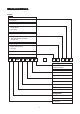
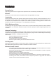
Nomenc la tur e Nomencla latur ture Indoor Others A : First issue Contoller Type L : Longertech E-scroll T : OYL E-Scroll U : OYL DC1P Air Treatment Devices & Control I : Negative Ion with wireless controller N : NTP with wireless controller X : Oxygen unit Market Region C : Export with CE mark U : UTL Spec.
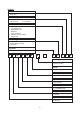
Outdoor Others A : First issue Contoller Type L : Longertech E-scroll T : OYL E-scroll U : OYLDC1P Air Treatment Devices & Control O G H I L S X : Standard unit : Low ambient unit : High ambient unit : Gold fins : Long piping unit : With H/L pressure switch : Oxygen unit Market Region C : Export with CE mark E : Export without marking U : UTL Spec.
Fea tur es eatur tures Energy Saving Total energy saved can be as high as 30% compared to the conventionally controlled units. Efficient McQuay DC Inverter series achieve excellent efficient with high EER & COP rating. Comfortable Users enjoy better comfort and quietness with inverter technology.
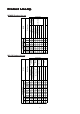
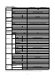
025CR 020CR 015CR Heat Pump Model 010CR ACOLA X ACOTA X ACILA X ACITA X X X ACOLA X X X X X ACILA X X X X ACOLA X X X X ACILA X X X X ACOUA X ACOLA X ACOTA X ACILA X ACITA X ACOUA X X X X X X X Nomenclature M5WMX Anti-Microbial Filter Air Filter (Titanium Oxide) X X X X X X X X X X X X X X X X X X X X X X X X X X X X X X 4 X CE Auto Restart Non-Thermal Plasma (NTP) Negative Ion X X X X X X X X X X X X X Gold Fin X A
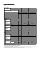
Specif ica tions Specifica ications General Data MODEL INDOOR UNIT M5WMX 015GR M5WMX 010GR OUTDOOR UNIT Btu/h NOMINAL COOLING CAPACITY NOMINAL HEATING CAPACITY M5LCX 010CR M5LCX 015CR 9,000 (3,700 - 12,000) 12,000 (3,700 - 15,000) W 2,638 (1,084 - 3,517) 3,517 (1,084 - 4,396) Btu/h 11,500 (4,000 - 15,000) 14,000 (4,000 - 17,000) W 3,370 (1,172 - 4,980) 4,103 (1,172 - 4,982) NOMINAL TOTAL INPUT POWER (COOLING) W 780 (300 - 1,100) 1,095 (300 - 1,780) NOMINAL TOTAL INPUT POWER (HEATING)
General Data MODEL INDOOR UNIT M5WMX 020GR M5WMX 025GR OUTDOOR UNIT M5LCX 020CR M5LCX 025CR Btu/h 18,000 (5,000 - 20,000) 21,000 (5,000 - 23,000) W 5,275 (1,465 - 5,862) 6,155 (1,465 - 6,741) Btu/h 19,000 (5,000 - 22,000) 22,000 (5,000 - 25,000) NOMINAL COOLING CAPACITY NOMINAL HEATING CAPACITY W 5,568 (1,465 - 6,155) 6,448 (1,465 - 7,034) NOMINAL TOTAL INPUT POWER (COOLING) W 1,636 2,150 NOMINAL TOTAL INPUT POWER (HEATING) W 1,652 2,200 NOMINAL RUNNING CURRENT (COOLING) A 7.
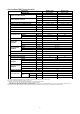
General Data (With Torque Control) MODEL INDOOR UNIT M5WMX 010GR M5WMX 015GR OUTDOOR UNIT M5LCX 010CR M5LCX 015CR Btu/h 9,500 (2,772 - 11,165) 12,000 (2,772 - 15,114) W 2,784 (812 - 3,272) 3,517 (812 - 4,430) Btu/h 11,500 (2,699 - 15,655) 13,000 (2,699 - 16,170) NOMINAL COOLING CAPACITY NOMINAL HEATING CAPACITY W 3,370 (791 - 4,588) 3,810 (791 - 4,739) NOMINAL TOTAL INPUT POWER (COOLING) W 820 (242 - 1,038) 1,100 (242 - 1,559) NOMINAL TOTAL INPUT POWER (HEATING) W 930 (231 - 1,455)
Components Data MODEL INDOOR UNIT M5WMX 010GR OUTDOOR UNIT M5LCX 010CR 1 Q'TY INDOOR FAN MOTOR ACRYLO NITRILE STYRENE MATERIAL DIRECT DRIVE DIAMETER mm/in LENGTH mm/in 97.0 / 3.8 717.5 / 28.2 SCR MOTOR TYPE 1 Q'TY IP24 INDEX OF PROTECTION (IP) PROPELLER FAN TYPE 1 Q'TY GLASS REINFORCED ACRLY STYRENE RESIN OUTDOOR FAN MATERIAL DIRECT DRIVE DIAMETER 406.0 / 16.
Components Data MODEL INDOOR UNIT M5WMX 020GR OUTDOOR UNIT M5LCX 020CR 1 Q'TY INDOOR FAN MOTOR ACRYLO NITRILE STYRENE MATERIAL DIRECT DRIVE DIAMETER mm/in LENGTH mm/in 108.0 / 4.3 810.0 / 32.9 SCR MOTOR TYPE 1 Q'TY IP54 INDEX OF PROTECTION (IP) PROPELLER TYPE 1 Q'TY GLASS REINFORCED ACRYL STYRENE RESIN OUTDOOR FAN MATERIAL DIRECT DRIVE DIAMETER 460.
Components Data (With Torque Control) MODEL INDOOR UNIT M5WMX 010GR OUTDOOR UNIT M5LCX 010CR 1 Q'TY INDOOR FAN MOTOR ACRYLO NITRILE STYRENE MATERIAL DIRECT DRIVE DIAMETER mm/in LENGTH mm/in 97 / 3.8 717.5 / 28.
Oper ating R ang e Opera Rang ange Ensure the operating temperature is in allowable range. Heatpump Heating Cooling Outdoor temp. (°CDB) Outdoor temp. (°CWB) 18 6 STD 46 35 STD 19 0 -9 15 21 27 15 24 Indoor temp. (°CWB) Indoor temp. (°CDB) Caution : The use of your air conditioner outside the range of working temperature and humidity can result in serious failure.
Outlines And Dimensions INDOOR UNIT MODEL : M5WMX 010GR / 015GR Note : Dimension in mm OUTDOOR UNIT MODEL : M5LCX 010CR / 015CR Note : Dimension in mm 12
INDOOR UNIT MODEL : M5WMX 020GR / 025GR MODEL A B 1062 M5WMX 020/025 GR C D E 304 220 912 294 F G H I J K 99 51 8 48 43 L M N O 354 403 160 138 160 Note : Dimension in mm OUTDOOR UNIT MODEL : M5LCX 020CR / 025CR FOR M5LCX025C/CR ONLY MODEL F G N O P Q R S T M5LCX 020 CR 855 A 628 328 508 181 B C D E 44 93 149 101 113 603 126 164 H I J K L M 17 49 32 3 23 73 75 M5LCX 025 CR 855 730 328 513 182 44 93 149 101 113 603 126 164 17 47 32 3 23
Electrical Da ta Data MODEL INDOOR UNIT M5WMX 010GR M5WMX 015GR OUTDOOR UNIT M5LCX 010CR M5LCX 015CR TYPE SCR INSULATION GRADE POWER SOURCE INDOOR MOTOR E V/Ph/Hz 230 / 1 / 50 RATED INPUT POWER W 38 40 RATED RUNNING CURRENT A 0.19 0.20 MOTOR OUTPUT W 17 POLES PERMANENT SPLIT CAPACITOR INSULATION GRADE OUTDOOR MOTOR B V/Ph/Hz 230 / 1 / 50 230 / 1 / 50 RATED INPUT POWER W 56 71 RATED RUNNING CURRENT A 0.24 0.
Electrical Data (With Torque Control) MODEL INDOOR UNIT M5WMX 010GR OUTDOOR UNIT M5LCX 010CR TYPE INDOOR MOTOR E V/Ph/Hz 230 / 1 / 50 RATED INPUT POWER W 38 40 RATED RUNNING CURRENT A 0.19 0.20 MOTOR OUTPUT W 17 POLES B V/Ph/Hz 230 / 1 / 50 RATED INPUT POWER W 56 71 RATED RUNNING CURRENT A 0.24 0.
Contr oller Controller G11 Remote Controller Temperature Setting On/Off Button • • Press Once to start the air conditioner • Press again to stop the unit To set the desired room temperature, press the button to increase or decrease the set temperature. • The temperature setting range is from 16°C to 30°C • Press both buttons simultaneously to toggle the temperature setting between °C and °F Personalised Setting • Press and hold the button for 3s to initiate personalized setting.
W iring Dia grams Diag INDOOR UNIT MODEL : M5WMX 010GR/015GR (WITH IONIZER) OUTDOOR UNIT MODEL : M5LCX 010CR/015CR 17
INDOOR UNIT MODEL : M5WMX 010GR/015GR (WITH NON-THERMAL PLASMA) OUTDOOR UNIT MODEL : M5LCX 010CR/015CR 18
INDOOR UNIT MODEL : M5WMX 020GR/025GR (WITH IONIZER) OUTDOOR UNIT MODEL : M5LCX 020CR/025CR 19
INDOOR UNIT MODEL : M5WMX 020GR/025GR (WITH NON-THERMAL PLASMA) OUTDOOR UNIT MODEL : M5LCX 020CR/025CR 20
Refrig er ant Cir cuit Dia gram efriger erant Circuit Diag MODEL : M5WMX 010GR/015GR c/w M5LCX 010CR/015CR 21
MODEL : M5WMX 020GR/025GR c/w M5LCX 020CR/025CR 22
Installa tion Installation INSTALLATION DIAGRAM 1. SELECTION OF LOCATION AND SPACE A) INDOOR UNIT Install the fan coil (indoor) unit at a location with the following requirements • Location is suitable for wiring, piping and drainage. • No obstruction of air flow into and out of unit where cooler air can be evenly distributed.(See fig. 1) • Ensure that air discharge is not short circuited with air intake. • Ensure that wall is sufficiently strong, rigid, flat, perpendicular and vibration free.
Figure 1 B) OUTDOOR UNIT As condensing temperature rises, evaporating temperature rises and cooling capacity drops. In order to achieve maximum cooling capacity, the location selected for outdoor unit should fulfill the following requirements: • Install the condensing (outdoor) unit in such a way that hot air distributed by the outdoor condensing unit cannot be drawn in again (as in the case of short circuit of hot discharge air). Allow sufficient space for maintenance around the unit.
• A place capable of bearing the weight of the outdoor unit and isolating noise and vibration. • A place protected from direct sunlight. Otherwise use an awning for protection, if necessary. • The location must not be susceptible to dust or oil mist. 2. INSTALLATION CLEARANCES • Outdoor units must be installed such that there is no short circuit of the hot discharge air or obstruction to smooth air flow. Select the coolest possible place where intake air should not be hotter than the outside temperature.
CAUTION : • If the condensing unit is operated in an atmosphere containing oils(including machine oils), salt(coastal area), sulphide gas(near hot spring, oil refinery plant), such substances may lead to failure of the unit. • If there is any obstacle higher than 2m, or if there is any obstruction at the upper part of the unit, please allow more space than the figure indicated in the above table. 3. DRILLING HOLES AND MOUNTING PLATE INSTALLATION Cautions: i) Please check the unit weight for each model.
4. INDOOR UNIT PREPARATION • The refrigerant piping can be routed to the unit in 5 directions, by using the cut outs in the unit casing. • Carefully bend the pipes to the required position to align with the hole. For right hand and rear side draw out, hold the bottom of the piping and fix direction before shaping it to the desired position. The condensation drain hose should be taped to the pipes with vinyl tape. The electrical cable can also be taped to the pipes. 5.
7. CONDENSED WATER DISPOSAL OF OUTDOOR UNIT (HEAT PUMP UNIT ONLY) • There are 2 holes on the base of Outdoor Unit for condensed water to flow out. Insert the drain elbow to one of the holes. • To install the drain elbow, first insert one portion of the hook to the base (portion A), then pull the drain elbow in the direction shown by the arrow while inserting the other portion to the base. After the installation, check to ensure that the drain elbow clings to base firmly.
8. WIRING Important: The figures shown in the table are for information purpose only. They should be checked and selected to comply with the local/national codes of regulations. This is also subject to the type of installation and conductors used. Model M5WMX 010G/015G Voltage range M5WMX 020G/025G 220V-240V / 1 Ph / 50Hz + Power supply cable size (mm2) 1.5 2.5 3 3 1.5 2.
9. REFRIGERANT PIPING A) Maximum Pipe Length and Maximum Number of Bends Always choose the shortest path for refrigerant piping and follow the recommendation as tabulated below: Model M5WMX010GR M5WMX015GR M5WMX020GR M5WMX025GR Maximum length, L (m/ft) 15/49 15/49 30/98 30/98 Max. elevation, H (m/ft) 5/16.4 5/16.4 8/26.2 8/26.2 Max.
• The exact length of pipe protruding from the face of the flare die is determined by the flaring tool. The table shows the use of an imperial die and rigid die. Pipe ∅, D (mm/in) 6.35 / 1/4” 9.52 / 3/8” 12.70 / 1/2” 15.88 / 5/8” 19.05 / 3/4” A (mm) Imperial 1.3 1.6 1.9 2.2 2.5 Rigid 0.7 1.0 1.3 1.7 2.0 Fix the pipe firmly on the flare die. Match the centers of both the flare die and the flaring punch, and tighten flaring punch fully.
10. SPECIAL PRECAUTION FOR R410A SPECIAL PRECAUTIONS WHEN DEALING WITH REFRIGERANT R410A UNIT 1) WHAT IS NEW REFRIGERANT R410A? R410A is a new HFC refrigerant which does not damage the ozone layer. The working pressure of this new refrigerant is 1.6 times higher than conventional refrigerant (R22), thus proper installation / servicing is essential.
d) When charging R410A, ensure that only liquid is being withdrawn from the cylinder or can. This is to ensure that only the original composition of R410A is being delivered into the system. The liquid composition can be different from the vapor composition. Invert cylinder without dip-pipe Dip-pipe Liquid withdrawal f) Normally, the R410A cylinder or can is being equipped with a dip pipe for liquid withdrawal.
11. VACUUMING AND CHARGING PURGING THE PIPING AND THE INDOOR UNIT Except for the outdoor unit which is pre-charged with refrigerant, the indoor unit and the refrigerant connection pipes must be air-purged because the air containing moisture that remains in the refrigerant cycle may cause malfunction of the compressor. • Remove the caps from the valve and the service port. • Connect the center of the charging gauge to the vacuum pump. • Connect the charging gauge to the service port of the 3-way valve.
Ser vicing And Maintenance Servicing ! Warning • Disconnect from the main power supply before servicing the air conditioner unit. • DO NOT pull out the power cord when the power is ON. This may cause serious electrical shocks which may result in fire hazards. 1 2 3 4 5 Off the unit Unscrew the air discharge housing Flip open the air discharge housing Clean the blower Close the air discharge housing and tighten it with screw Service Parts Maintenance Procedures Indoor Air Filters 1.
Service Parts Maintenance Procedures Period Electrical 1.Check voltage, current and wiring. 2.Check faulty contacts caused by loose connections, foreign matters, etc. Every 2 months Every 2 months Compressor 1.No maintenance needed if refrigerant circuit remains sealed. However, check for refrigerant leak at joints and fittings. Every 6 months. Compressor Lubrication 1.Oil is factory charged. Not necessary to add oil if circuit remains sealed. No maintenance required. Fan Motors Lubrication 1.
Troub leshooting oubleshooting When a malfunction of the air conditioner unit is detected, immediately switch off the main power supply before proceeding with the following troubleshooting procedures. The following are common fault conditions and simple troubleshooting tips. If any other fault conditions which are not listed occur, contact your nearest local dealer. DO NOT attempt to troubleshoot the unit by yourself.
Diagnostic Guidelines By means of pressure reading: High side Low side ● ● High side Low side High side Low side High side Low side High side Low side Probable cause Too high A little high Normal Circuit Too low Data A little low Pressure ● ● ● ● ● ● ● 1. 2. 3. 4. Overcharged with refrigerant. Non-condensable gases in refrigerant circuit (e.g. air) Obstructed air-intake / discharge. Hot air short circuiting in outdoor unit. 1. Poor compression / no compression (compressor defective) 2.
By means of diagnostic flow chart: Generally, there are two kinds of problems, i.e. starting failure and insufficient cooling/heating. “Starting failure” is caused by electrical defect while improper application or defects in refrigerant circuit causes “Insufficient cooling / heating”. i) Diagnosis of Electric Circuit The most common causes of air conditioner failure to “start” are : a) Voltage not within ±10% of rated voltage. b) Power supply interrupted. c) Improper control settings.
ii ) Diagnosis of Refrigerant Circuit / Application There might be some causes where the unit starts running but does not perform satisfactorily, i.e. insufficient cooling. Judgement could be made by measuring temperature difference of indoor unit’s intake and discharge air as well as running current. Satisfactory operation with temperature difference of air intake & discharge of indoor unit 8°C to 13°C.
Satisfactory operation with temperature difference of air intake & discharge of indoor unit 14°C to 20°C.
INDICATOR LIGHTS Inverter Unit IR SIGNAL RECEIVER When there is infrared remote control operating signal, the signal receiver on indoor unit will made a (beep) for signal acceptance confirmation. IR Receiver COOLING / HEATPUMP UNIT The table below shows the LED indicator light for air conditioner unit under normal operation and fault condition. The LED indicator lights are located at the middle of the air conditioner unit.
Compressor Stopped Troubleshooting Instructions 1 (Applicable to Inverter System Only) Keep the Main Power Supply ON Open up the Outdoor Unit’s Top Panel or Service Panel DO NOT TOUCH ANY OF THE WIRES INSIDE THE UNIT! Notice the Yellow LED on the P.C.
Normal Running Mode Condition 2 (Applicable to Inverter System Only) If the air conditioner unit has no faulty indications and the compressor is running at normal mode, the outdoor P.C.Board’s LED indication will blink at a slower paste. The table below shows the significant meaning of different running mode and limitation for this air conditioner unit. One must not attempt to see the LED indication blinking unless instructed to do so.
Exploded Vie w And P ar ts List iew Par arts MODEL : M5WMX 010GR/015GR Related Nomenclature No. Description Part Number 1 2 3 4 5 ASSY, CHASSIS 10/15G MOTOR, MWMX10/15G-501-WL 17W WELLING BLOWER CROSS FLOW WM10/15G G97-717.5 FAN BUSH C/FLOW BLACK ASSY.
MODEL : M5WMX 020GR/025GR No. Description Part Number 1 2 3 4 5 6 7 8 9 10 ASSY, CHASSIS 10/15G ASSY, FAN MOTOR 20/25G FAN CROSS FLOW, WM20/25F FAN BUSH C/FLOW GREY ASSY, COIL WM20G/GR / 5WM25G/GR CLAMP, PIPING 20/25G ASSY, DRAIN PAN 20/25G DRAIN HOSE ASSY WM20C/25C(700mmL) ASSY.
MODEL : M5LCX 010CR/015CR No. 1 2 3 4 5 6 7 8 9 10 11 12 13 14 Description Related Model Part Number ASSY.
MODEL : M5LCX 020CR/025CR No. 1 2 3 4 5 6 7 8 9 10 11 12 13 14 15 16 17 Description Related Model Part Number ASSY, BASE PAN (5SLX20/25CR) ASSY, OUTDOOR COIL (5SLX20/25CR) COMPRESSOR, 5CS130XCC03 MATSUSHITA ASSY, VALVE BRACKET (5SLX 20CR) ASSY, VALVE BRACKET (5SLX 25CR) ASSY., 3 WAYS VALVE 1/2" ASSY., 3 WAYS VALVE 5/8" ASSY., 2 WAYS VALVE 1/4" VALVE, REV 4 WAY SHF-7H-34U(RK) SHANHUA ASSY.