
Unit installation


Table Of Contents
- Introduction
- Installation
- Physical Data
- Electrical Data
- Dimensional Data
- Startup
- Operation
- Global UNT Controller Installation and Operation
- General Description
- Optional Sensors
- Sensors and Transducers
- Control Wiring
- External Voltage Inputs
- Interlock Wiring
- Unit Set Points and Calibration
- Optional Sensors
- Field Wiring
- Power Wiring
- Power Supplies
- Analog input signals
- Digital input signals
- Remote Stop/Start
- Chilled Water Flow Switch
- Digital Outputs
- External Alarm Annunciator Circuitry
- PC Connection
- Software Identification
- Controller Inputs /Outputs
- Additional Global UNT Features
- Alarms
- Zone Terminal (Optional)
- Zone Terminal Glossary
- UNT Troubleshooting Chart
- MicroTech Controller Installation and Operation
- Sensors and transducers
- Control wiring
- Remote 4-20 milliamp signals
- Interlock wiring
- Unit set points and calibration
- Modem kit
- Lead-Lag
- Field Wiring
- Power Wiring
- Power Supplies
- Analog Input Signals
- Digital Input Signals
- Remote Stop/Start
- Chilled Water Flow Switch
- Digital Outputs
- Chilled Water Pump Relay
- External Alarm Annunciator Circuitry
- PC Connection
- Telephone line
- Software Identification
- Controller Inputs /Outputs
- Reset Options
- Soft Loading
- Manual Operation
- Compressor Staging
- Head Pressure Control
- Pumpdown Control
- Safety Systems
- Circuit Alarm Conditions
- System Alarm Conditions
- Sequence of Operation
- Start-Up and Shutdown
- Keypad / Display
- Menu Descriptions
- Trouble Analysis for the MicroTech
- Test Procedures
- Unit Maintenance
- Service
IOMM AGZ-3 AGZ 035A through 065A 9
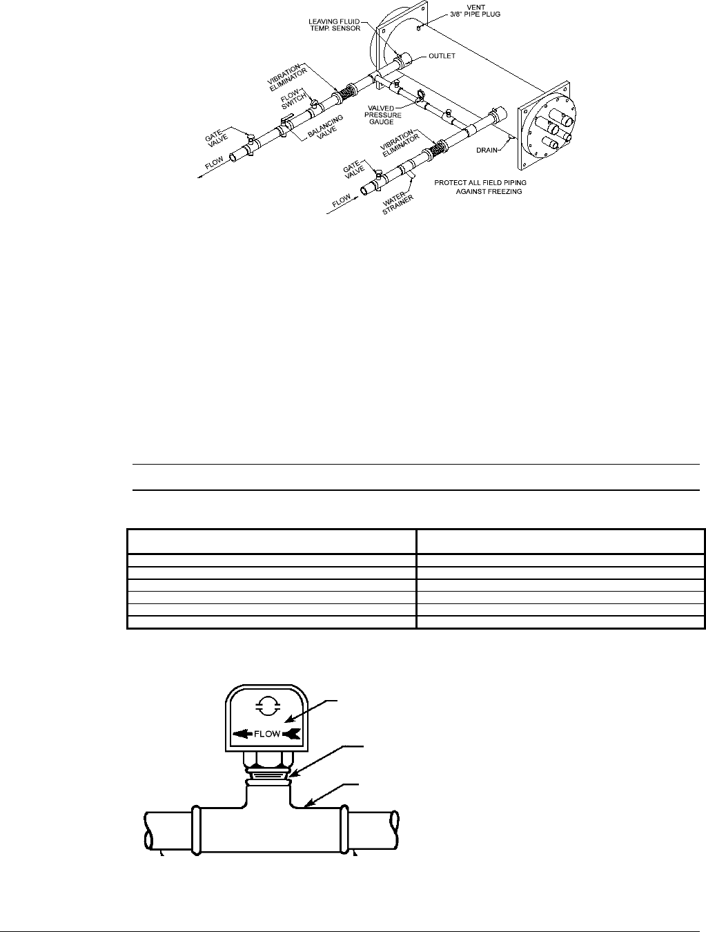
Figure 5, Typical Field Evaporator Water Piping
Flow Switch
Mount a water flow switch in either the entering or leaving water line to shut down the unit when
water flow is interrupted. A flow switch is an equipment protection control and should never be used
to cycle a unit.
A flow switch is available from McQuay (part number 017503300). It is a “paddle” type switch and
adaptable to any pipe size from 3” (76mm) to 8” (203mm) nominal. Certain minimum flow rates are
required to close the switch and are listed in Table 3. Installation should be as shown in Figure 6.
Connect the normally open contacts of the flow switch in the unit control center at terminals 5 and 6.
There is also a set of normally closed contacts on the switch that can be used for an indicator light or
an alarm to indicate when a “no flow” condition exists. Freeze protect any flow switch that is
installed outdoors.
NOTE: Differential pressure switches are not recommended for outdoor installation.
Table 3, Flow Switch Minimum Flow Rates
NOMINAL PIPE SIZE MINIMUM REQUIRED FLOW TO
INCHES (MM) ACTIVATE SWITCH - GPM (L/S)
2 (50.8) 18.80 (1.20)
2 1/2 (63.50 24.30 (1.50)
3 (76.20 30.00 (1.90)
4 (101.6) 39.70 (2.50)
5 (127.0) 58.70 (3.70)
6 (152.4) 79.20 (5.00)
Figure 6, Flow Switch Installation
Flow direction marked
on switch
1" (25mm) NPT flow
switch connection
Tee