
Unit installation


Table Of Contents
- Introduction
- Installation
- Physical Data
- Electrical Data
- Dimensional Data
- Startup
- Operation
- Global UNT Controller Installation and Operation
- General Description
- Optional Sensors
- Sensors and Transducers
- Control Wiring
- External Voltage Inputs
- Interlock Wiring
- Unit Set Points and Calibration
- Optional Sensors
- Field Wiring
- Power Wiring
- Power Supplies
- Analog input signals
- Digital input signals
- Remote Stop/Start
- Chilled Water Flow Switch
- Digital Outputs
- External Alarm Annunciator Circuitry
- PC Connection
- Software Identification
- Controller Inputs /Outputs
- Additional Global UNT Features
- Alarms
- Zone Terminal (Optional)
- Zone Terminal Glossary
- UNT Troubleshooting Chart
- MicroTech Controller Installation and Operation
- Sensors and transducers
- Control wiring
- Remote 4-20 milliamp signals
- Interlock wiring
- Unit set points and calibration
- Modem kit
- Lead-Lag
- Field Wiring
- Power Wiring
- Power Supplies
- Analog Input Signals
- Digital Input Signals
- Remote Stop/Start
- Chilled Water Flow Switch
- Digital Outputs
- Chilled Water Pump Relay
- External Alarm Annunciator Circuitry
- PC Connection
- Telephone line
- Software Identification
- Controller Inputs /Outputs
- Reset Options
- Soft Loading
- Manual Operation
- Compressor Staging
- Head Pressure Control
- Pumpdown Control
- Safety Systems
- Circuit Alarm Conditions
- System Alarm Conditions
- Sequence of Operation
- Start-Up and Shutdown
- Keypad / Display
- Menu Descriptions
- Trouble Analysis for the MicroTech
- Test Procedures
- Unit Maintenance
- Service
IOMM AGZ-3 AGZ 035A through 065A 85
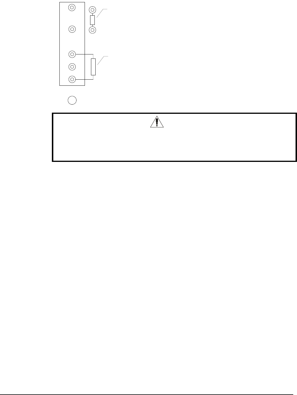
Figure 32, Output Board Relay Socket
1
2
3
4
5
LED
Fuse
Test Resistor
330-680 Ohm
*250V ~ 50/60 Hz
*120V ~ 50/60 Hz
WARNING
Electric shock hazard. Can cause severe injury or death. Even when power to
the panel is off, solid-state relay socket terminals 1 and 2 on the output board
could be connected to high voltage. Avoid them.
One LED Out
If one of the Output Board LEDs fails to illuminate when the MCB is commanding the associated
output to energize, perform the following procedure:
1.
Remove power from the controller by opening CB1. Swap the suspect relay with a known good
relay. Try to choose a relay that will not affect unit operation. Restore power by closing CB1.
If the LED does not light, go to step 2.
If the LED lights, the suspect relay is defective.
2.
Remove power from the controller. Check the ribbon cable and connections between the OB and
the MCB. Look for bent pins.
If the cable and connections are intact, go to step 3.
3.
Remove the relay from the suspect socket. Install a 330-680 ohm resistor between terminals 3
and 5 as shown in Figure 32. Restore power by placing CB1 to the ON position. The LED should
light regardless of the controller’s command.
If the output LED illuminates, it is likely that the MCB is defective.
If the output LED does not illuminate, the output board is defective.
All LEDs Out
If the MCB is commanding at least two outputs to energize and none of the Output Board LEDs are
lit, perform the following procedure:
1.
Verify that 5Vdc is present at the Output Board’s power terminals.
If 5Vdc is not present, go to step 2.
If 5Vdc is present, check the ribbon cable and connections between the output board and MCB.
Look for bent pins. If the cable and connections are intact, the Output Board or the MCB is
defective.