
Unit installation


Table Of Contents
- Introduction
- Installation
- Physical Data
- Electrical Data
- Dimensional Data
- Startup
- Operation
- Global UNT Controller Installation and Operation
- General Description
- Optional Sensors
- Sensors and Transducers
- Control Wiring
- External Voltage Inputs
- Interlock Wiring
- Unit Set Points and Calibration
- Optional Sensors
- Field Wiring
- Power Wiring
- Power Supplies
- Analog input signals
- Digital input signals
- Remote Stop/Start
- Chilled Water Flow Switch
- Digital Outputs
- External Alarm Annunciator Circuitry
- PC Connection
- Software Identification
- Controller Inputs /Outputs
- Additional Global UNT Features
- Alarms
- Zone Terminal (Optional)
- Zone Terminal Glossary
- UNT Troubleshooting Chart
- MicroTech Controller Installation and Operation
- Sensors and transducers
- Control wiring
- Remote 4-20 milliamp signals
- Interlock wiring
- Unit set points and calibration
- Modem kit
- Lead-Lag
- Field Wiring
- Power Wiring
- Power Supplies
- Analog Input Signals
- Digital Input Signals
- Remote Stop/Start
- Chilled Water Flow Switch
- Digital Outputs
- Chilled Water Pump Relay
- External Alarm Annunciator Circuitry
- PC Connection
- Telephone line
- Software Identification
- Controller Inputs /Outputs
- Reset Options
- Soft Loading
- Manual Operation
- Compressor Staging
- Head Pressure Control
- Pumpdown Control
- Safety Systems
- Circuit Alarm Conditions
- System Alarm Conditions
- Sequence of Operation
- Start-Up and Shutdown
- Keypad / Display
- Menu Descriptions
- Trouble Analysis for the MicroTech
- Test Procedures
- Unit Maintenance
- Service
IOMM AGZ-3 AGZ 035A through 065A 79
Following is the normal start-up sequence that the three status LED’s should follow when power is
applied to the MCB:
1.
The red (“Reset”) LED turns on and remains on for approximately 5 seconds. During this period
the MCB performs a self-test.
2.
The red LED turns off and the green (“Running”) LED turns on. This indicates that the
microprocessor has passed the self-test and is functioning properly.
3.
The amber (“Active”) LED remains off continually if no alarm conditions exist in the network. If
alarm conditions exist, the amber LED will flash as shown in Table 5.
If the above sequence does not occur after power is applied to the controller, there is a problem with
the MCB or its power supply.
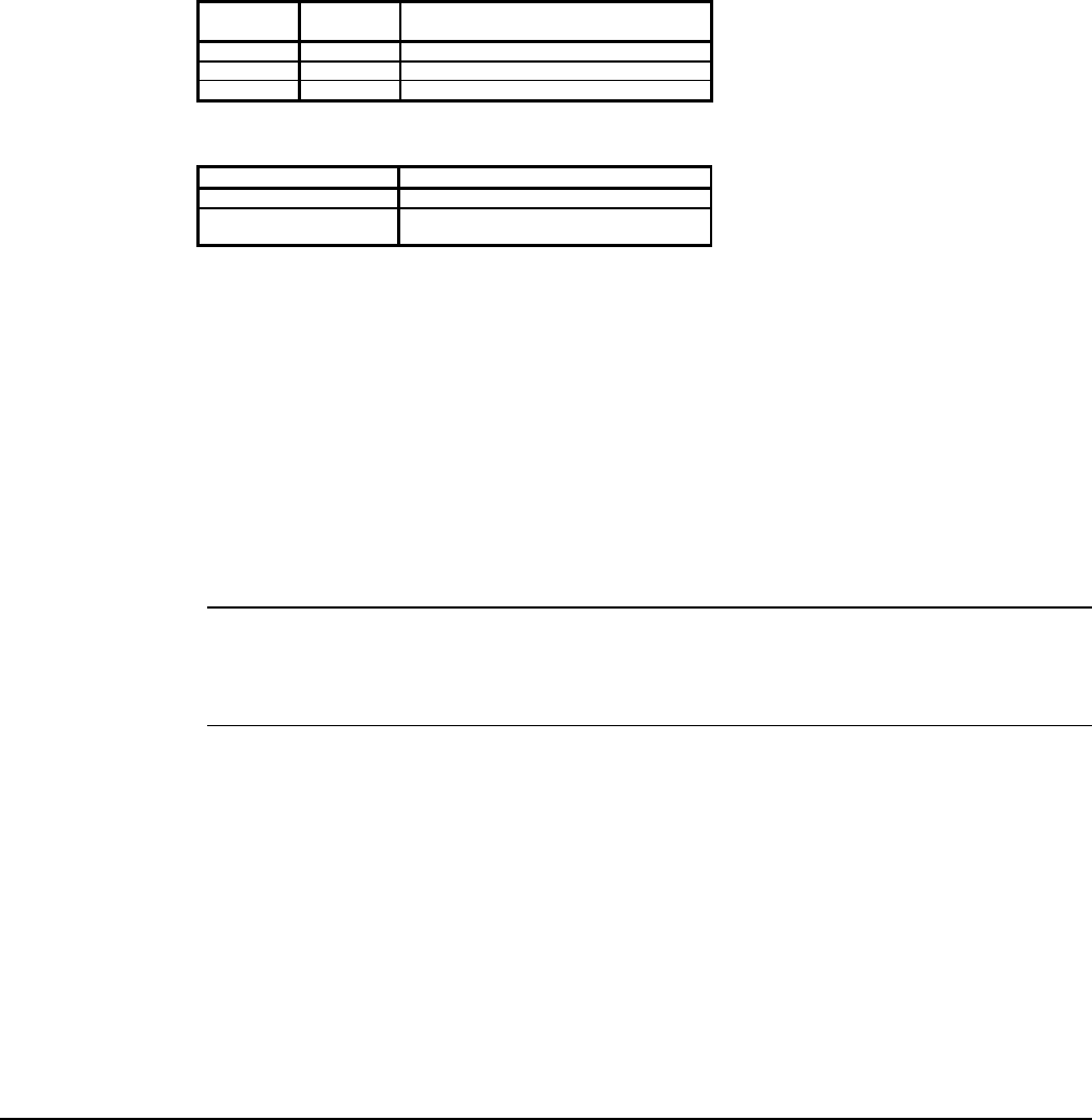
Table 51 and Table 52 summarize the green, red, and amber status LED indications.
Table 51, Green and Red Status LED Indication
Green
LED State
Red
LED State
Indication
Off Off No power to MCB
Off On* Self-test failure or power supply problem
On Off MCB operating normally
* For longer than 5 seconds.
Table 52, Amber Status LED Indication
Amber LED State Indication
Off Normal operation
On 1/2 second;
Off 1/2 second
Alarm condition
Keypad/LCD Display Connection
The MCB receives input commands and operating parameters from the keypad and sends requested
information to the display through the Keypad/LCD Display port via a plug-in ribbon cable.
Hex Switches
The MCB includes two hex (hexadecimal) switches that are used to set the network address.
The HI and LO hex switches are shown in Figure 30. A “hex switch setting” is defined as the HI
switch digit followed by the LO switch digit. For example, a hex switch setting of 2F would have the
HI switch set to “2” and the LO switch set to “F.”
Note: You can change the setting of a hex switch with a 3/32-inch tip slotted-blade
screwdriver. If a hex switch setting is changed, power to the MCB must be cycled in order to
enter the new setting into memory. This can be done by turning the panel’s power switch off
and then back on.