
Unit installation


Table Of Contents
- Introduction
- Installation
- Physical Data
- Electrical Data
- Dimensional Data
- Startup
- Operation
- Global UNT Controller Installation and Operation
- General Description
- Optional Sensors
- Sensors and Transducers
- Control Wiring
- External Voltage Inputs
- Interlock Wiring
- Unit Set Points and Calibration
- Optional Sensors
- Field Wiring
- Power Wiring
- Power Supplies
- Analog input signals
- Digital input signals
- Remote Stop/Start
- Chilled Water Flow Switch
- Digital Outputs
- External Alarm Annunciator Circuitry
- PC Connection
- Software Identification
- Controller Inputs /Outputs
- Additional Global UNT Features
- Alarms
- Zone Terminal (Optional)
- Zone Terminal Glossary
- UNT Troubleshooting Chart
- MicroTech Controller Installation and Operation
- Sensors and transducers
- Control wiring
- Remote 4-20 milliamp signals
- Interlock wiring
- Unit set points and calibration
- Modem kit
- Lead-Lag
- Field Wiring
- Power Wiring
- Power Supplies
- Analog Input Signals
- Digital Input Signals
- Remote Stop/Start
- Chilled Water Flow Switch
- Digital Outputs
- Chilled Water Pump Relay
- External Alarm Annunciator Circuitry
- PC Connection
- Telephone line
- Software Identification
- Controller Inputs /Outputs
- Reset Options
- Soft Loading
- Manual Operation
- Compressor Staging
- Head Pressure Control
- Pumpdown Control
- Safety Systems
- Circuit Alarm Conditions
- System Alarm Conditions
- Sequence of Operation
- Start-Up and Shutdown
- Keypad / Display
- Menu Descriptions
- Trouble Analysis for the MicroTech
- Test Procedures
- Unit Maintenance
- Service
78 AGZ 035A through 065A IOMM AGZ-3
Trouble Analysis for the MicroTech
Microprocessor Control Board
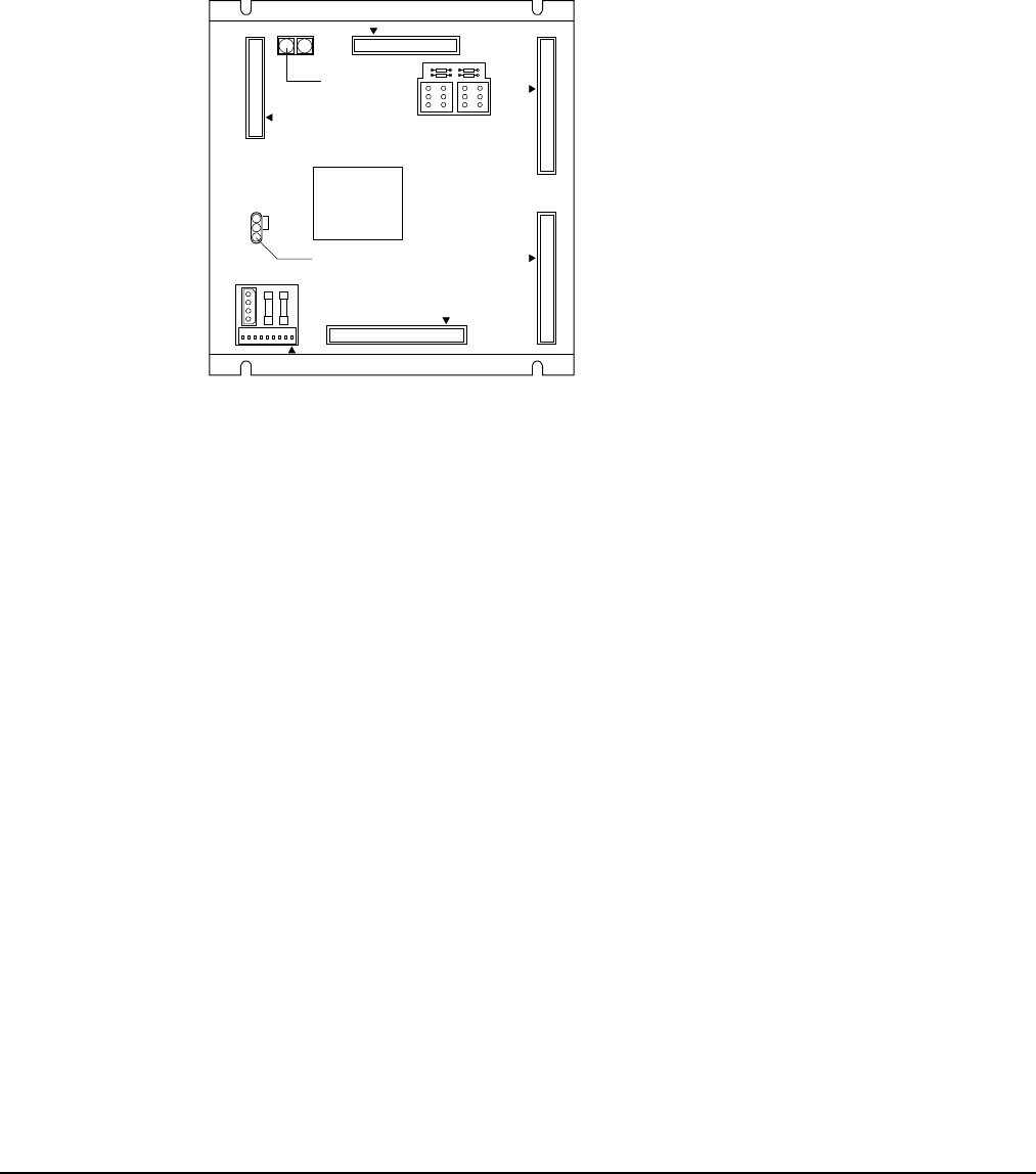
The Microprocessor Control Board (MCB) is shown in Figure 29. It contains a microprocessor that is
preprogrammed with the software required to monitor and control the chiller. The various MCB
connections and components are described below.
Figure 29, Microprocessor Control Board (MCB)
RUNNING
RESET
ACTIVE OUTPUT 0
CPU
STATUS
POWER FUSES
[BUSSMAN GDC-T2A]
POWER IN
[18-24 VCT]
AC AC GND GND
AUX
/
OUT
DIGITAL OUTPUTS
ANALOG INPUTS DIGITAL INPUTS
HI
ADDRESS
LO
KEYPAD
/
LCD DISPLAY
COMMUNICATIONS
PORT A PORT B
[FUSE: BUSSMAN MCR-1/4]
FUSE 1
2
3
4
Hex switches
Microprocessor status LED's
EXPANSION BUS
Digital Inputs Connection
The MCB receives digital inputs from the Analog Digital Input (ADI) board through the Digital
Inputs connector via a plug-in ribbon cable. The ADI board conditions these inputs.
Analog Inputs Connection
The MCB receives conditioned analog inputs from the ADI board through the Analog Inputs
connector via a plug-in ribbon cable. The ADI board conditions these inputs. After having been
conditioned, all analog inputs enter the MCB through the Analog Inputs port as 0–5Vdc signals.
Digital Outputs Connection
After processing all input conditions, the MCB sends the appropriate output signals to output devices
through the Digital Outputs port via a plug-in ribbon cable.
Power In Connector
The MCB receives 18Vac, center-tapped power from transformer T4 through the Power In Connector.
This power drives all logic and communications circuitry.
Power Fuses
Two identical 2-amp fuses are located to the right of the Power In connector. These fuses are in the
MCB power supply circuit.
Microprocessor Status LEDs
The green, red, and amber LEDs on the MCB provide information about the operating status of the
microprocessor. The amber LED also indicates the existence of alarm conditions.