
Unit installation


Table Of Contents
- Introduction
- Installation
- Physical Data
- Electrical Data
- Dimensional Data
- Startup
- Operation
- Global UNT Controller Installation and Operation
- General Description
- Optional Sensors
- Sensors and Transducers
- Control Wiring
- External Voltage Inputs
- Interlock Wiring
- Unit Set Points and Calibration
- Optional Sensors
- Field Wiring
- Power Wiring
- Power Supplies
- Analog input signals
- Digital input signals
- Remote Stop/Start
- Chilled Water Flow Switch
- Digital Outputs
- External Alarm Annunciator Circuitry
- PC Connection
- Software Identification
- Controller Inputs /Outputs
- Additional Global UNT Features
- Alarms
- Zone Terminal (Optional)
- Zone Terminal Glossary
- UNT Troubleshooting Chart
- MicroTech Controller Installation and Operation
- Sensors and transducers
- Control wiring
- Remote 4-20 milliamp signals
- Interlock wiring
- Unit set points and calibration
- Modem kit
- Lead-Lag
- Field Wiring
- Power Wiring
- Power Supplies
- Analog Input Signals
- Digital Input Signals
- Remote Stop/Start
- Chilled Water Flow Switch
- Digital Outputs
- Chilled Water Pump Relay
- External Alarm Annunciator Circuitry
- PC Connection
- Telephone line
- Software Identification
- Controller Inputs /Outputs
- Reset Options
- Soft Loading
- Manual Operation
- Compressor Staging
- Head Pressure Control
- Pumpdown Control
- Safety Systems
- Circuit Alarm Conditions
- System Alarm Conditions
- Sequence of Operation
- Start-Up and Shutdown
- Keypad / Display
- Menu Descriptions
- Trouble Analysis for the MicroTech
- Test Procedures
- Unit Maintenance
- Service
74 AGZ 035A through 065A IOMM AGZ-3
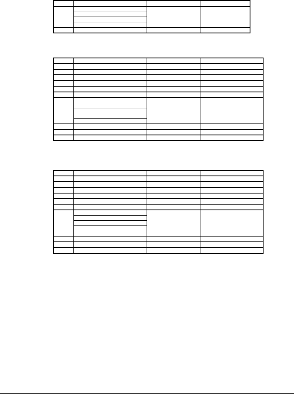
Table 33, MENU 13 Control Mode
Screen Display Factory Setpoint Range
Manual Unit Off
Automatic
Manual Staging
1 Manual Unit Off
2 Manual Stage=xx 0 1 - 8
Table 34, MENU 14 Lvg Evap Spts
Values for R-22 refrigerant, ( ) indicates Centigrade values
Screen Display Factory Setpoint Range
1 Actv Spt=xxx.x °F (°C) Not Changeable
2 Lvg Evap=xxx.x °F (°C) 44 (6.7) 10 - 80 (-12.2 - 26.7)
3 CntrlBand x.x °F (°C) 3.0 (1.6) 1.0 - 5.0 (0.5 - 2.7)
4 StartUpD-T= x.x °F (°C) 3.0 (1.6) 1.0 - 5.0 (0.5 - 2.7)
5 ShutDn D-T= x.x °F (°C) 1.5 (0.8) 0.0 - 3.0 (0.0 - 1.6)
6 MaxPullDn= x.x °F (°C) 0.5 (0.2) 0.1 - 1.0 (0.0 - 0.5)
ResetOpt=None
Return
4-20 Ma
Network
7
Ice
None
8 ResetSig= xx.xma Not Changeable
9 MaxChWRst=xx.x °F (°C) 10.0 (5.5) 0.0 - 45.0 (0.0 - 25.0)
10 ReturnSpt= xx.x °F (°C) 54.0 (12.3) 15.0 - 80.0 (-9.4 - 26.7)
[ ] the minus sign is not displayed with three digit numbers
Table 35, MENU 14 Lvg Evap Spts
Values for 134a refrigerant, ( ) indicates Centigrade values
Screen Display Factory Setpoint Range
1 Actv Spt=xxx.x °F (°C) Not Changeable
2 Lvg Evap=xxx.x °F (°C) 44 (6.7) 10 - 80 (-6.6 - 26.7)
3 CntrlBand x.x °F (°C) 3.0 (1.6) 1.0 - 5.0 (0.5 - 2.7)
4 StartUpD-T= x.x °F (°C) 3.0 (1.6) 1.0 - 5.0 (0.5 - 2.7)
5 ShutDn D-T= x.x °F (°C) 1.5 (0.8) 0.0 - 3.0 (0.0 - 1.6)
6 MaxPullDn= x.x °F (°C) 0.5 (0.2) 0.1 - 1.0 (0.0 - 0.5)
ResetOpt=None
Return
4-40 Ma
Network
7
Ice
None
8 ResetSig= xx.xma Not Changeable
9 MaxChWRst=xx.x °F (°C) 10.0 (5.5) 0.0 - 45.0 (0.0 - 25.0)
10 ReturnSpt= xx.x °F (°C) 54.0 (12.3) 15.0 - 80.0 (-9.4 - 26.7)
[ ] the minus sign is not displayed with three digit numbers