
Unit installation


Table Of Contents
- Introduction
- Installation
- Physical Data
- Electrical Data
- Dimensional Data
- Startup
- Operation
- Global UNT Controller Installation and Operation
- General Description
- Optional Sensors
- Sensors and Transducers
- Control Wiring
- External Voltage Inputs
- Interlock Wiring
- Unit Set Points and Calibration
- Optional Sensors
- Field Wiring
- Power Wiring
- Power Supplies
- Analog input signals
- Digital input signals
- Remote Stop/Start
- Chilled Water Flow Switch
- Digital Outputs
- External Alarm Annunciator Circuitry
- PC Connection
- Software Identification
- Controller Inputs /Outputs
- Additional Global UNT Features
- Alarms
- Zone Terminal (Optional)
- Zone Terminal Glossary
- UNT Troubleshooting Chart
- MicroTech Controller Installation and Operation
- Sensors and transducers
- Control wiring
- Remote 4-20 milliamp signals
- Interlock wiring
- Unit set points and calibration
- Modem kit
- Lead-Lag
- Field Wiring
- Power Wiring
- Power Supplies
- Analog Input Signals
- Digital Input Signals
- Remote Stop/Start
- Chilled Water Flow Switch
- Digital Outputs
- Chilled Water Pump Relay
- External Alarm Annunciator Circuitry
- PC Connection
- Telephone line
- Software Identification
- Controller Inputs /Outputs
- Reset Options
- Soft Loading
- Manual Operation
- Compressor Staging
- Head Pressure Control
- Pumpdown Control
- Safety Systems
- Circuit Alarm Conditions
- System Alarm Conditions
- Sequence of Operation
- Start-Up and Shutdown
- Keypad / Display
- Menu Descriptions
- Trouble Analysis for the MicroTech
- Test Procedures
- Unit Maintenance
- Service
72 AGZ 035A through 065A IOMM AGZ-3
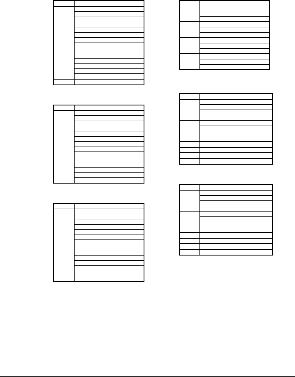
Table 21, MENU 1 Chiller Status
Screen Display
OFF: Manual Mode
OFF: System Sw
OFF: Remote Comm
OFF: Remote Sw
OFF: Time Clock
OFF: Alarm
OFF: PumpDnSw's
Starting
WaitForFlow
WaitForLoad
StageUp
StageDn
Stage
1
Manual
2 InterStg=xxx sec
Table 22, MENU 2 Circ #1 Status
Screen Display
OFF: SystemSw
OFF: ManualMde
OFF: Alarm
OFF: PumpDwnSw
OFF: CycleTime xx
OFF: Ready
PumpingDown
OpenSolenoid
% Capacity
Starting
LowAmbStart
1
Table 23, MENU 3 Circ #2 Status
Screen Display
OFF: SystemSw
OFF: ManualMde
OFF: Alarm
OFF: PumpDwnSw
OFF: CycleTime xx
OFF: Ready
PumpingDown
OpenSolenoid
% Capacity
Starting
LowAmbStart
1
Table 24, MENU 4 Water Temp's
Screen Display
Lvg Evap= xxx.x °F (°C)
Short °F (°C)1
Open °F (°C)
Ent Evap= xxx.x °F (°C)
Short °F (°C)2
Open °F (°C)
D-T Evap
Short °F (°C)3
Open °F (°C)
4
Table 25, MENU 5 Circ #1 Pres's
Screen Display
Evap= xxx.x psi(kPa) xx°F (°C)
Evap 145 +psi(kPa) **°F (°C)
Open N/A ** °F (°C)
1
Short N/A **°F
Cond xxx.x psi (kPa) xxx°
Cond 450+ psi (kPa) xxx°
Open N/A ** °F (°C)
2
Short N/A **F
3 MinCondPr = 0#
4 MaxCondPr = 0#
5 LiftD_P= psi
6 Cond Fan Stage = x
Table 26, MENU 6 Circ #2 Pres's
Screen Display
Evap= xxx.x psi(kPa) xx°F (°C)
Evap 145 +psi(kPa) **°F (°C)
Open N/A ** F (C)
1
Short N/A **F
Cond xxx.x psi (kPa) xxx°
Cond 450+ psi (kPa) xxx°
Open N/A ** °F (°C)
2
Short N/A **°F
3 MinCondPr = 0#
4 MaxCondPr = 0#
5 LiftD_P= psi
6 Cond Fan Stage = x
Menus for the AGZ MicroTech Controller