
Unit installation


Table Of Contents
- Introduction
- Installation
- Physical Data
- Electrical Data
- Dimensional Data
- Startup
- Operation
- Global UNT Controller Installation and Operation
- General Description
- Optional Sensors
- Sensors and Transducers
- Control Wiring
- External Voltage Inputs
- Interlock Wiring
- Unit Set Points and Calibration
- Optional Sensors
- Field Wiring
- Power Wiring
- Power Supplies
- Analog input signals
- Digital input signals
- Remote Stop/Start
- Chilled Water Flow Switch
- Digital Outputs
- External Alarm Annunciator Circuitry
- PC Connection
- Software Identification
- Controller Inputs /Outputs
- Additional Global UNT Features
- Alarms
- Zone Terminal (Optional)
- Zone Terminal Glossary
- UNT Troubleshooting Chart
- MicroTech Controller Installation and Operation
- Sensors and transducers
- Control wiring
- Remote 4-20 milliamp signals
- Interlock wiring
- Unit set points and calibration
- Modem kit
- Lead-Lag
- Field Wiring
- Power Wiring
- Power Supplies
- Analog Input Signals
- Digital Input Signals
- Remote Stop/Start
- Chilled Water Flow Switch
- Digital Outputs
- Chilled Water Pump Relay
- External Alarm Annunciator Circuitry
- PC Connection
- Telephone line
- Software Identification
- Controller Inputs /Outputs
- Reset Options
- Soft Loading
- Manual Operation
- Compressor Staging
- Head Pressure Control
- Pumpdown Control
- Safety Systems
- Circuit Alarm Conditions
- System Alarm Conditions
- Sequence of Operation
- Start-Up and Shutdown
- Keypad / Display
- Menu Descriptions
- Trouble Analysis for the MicroTech
- Test Procedures
- Unit Maintenance
- Service
IOMM AGZ-3 AGZ 035A through 065A 7
Vibration Isolators
Vibration isolators are recommended for all roof mounted installations or wherever vibration
transmission is a consideration.
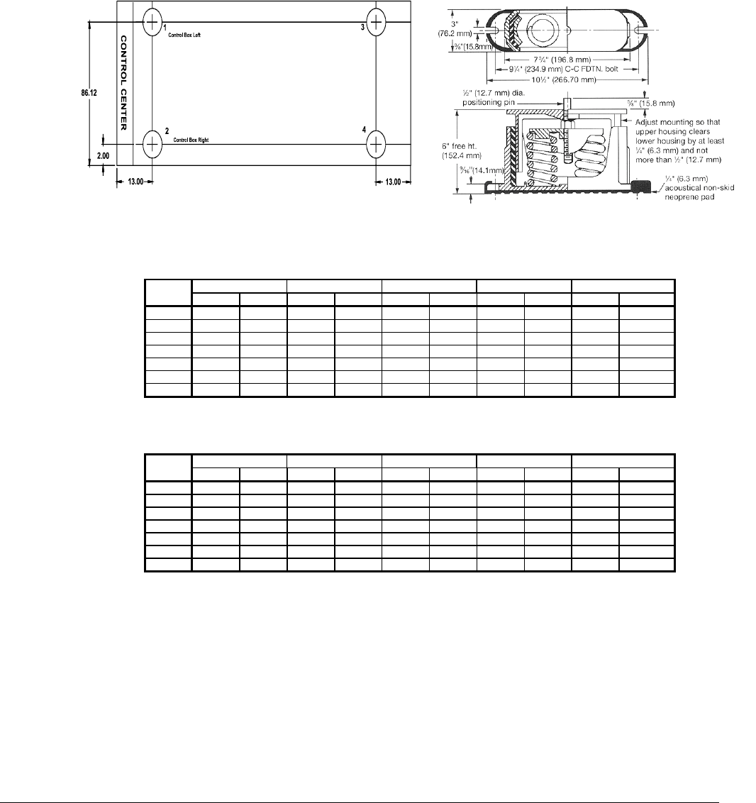
Table 1 and Table 2 list isolator point loads for all unit sizes. Figure 4 shows isolator locations. See
Dimensional Data for detailed dimensions required to secure each isolator to the mounting surface.
The spring flex isolators are white type CP2-32, McQuay kit number 350014821 provides the
required four per unit.
Figure 4, Isolator Locations Spring Isolator Dimensions
Table 1 , Isolator Loads At Each Mounting Location With Aluminum Fins
1234Total Unit
Unit
Size
lb Kg lb Kg lb Kg lb Kg lb Kg
035AS 850 386 960 435 785 356 885 401 3480 1579
040AS 864 392 974 442 797 362 900 408 3535 1603
045AS 928 421 1048 475 858 389 966 438 3800 1724
050AS 940 426 1062 482 868 394 980 445 3850 1746
055AS 990 449 1118 507 915 415 1032 468 4055 1839
060AS 1006 456 1134 514 928 421 1047 475 4115 1867
065AS 1050 476 1184 537 970 440 1091 495 4295 1948
Table 2, Isolator Loads At Each Mounting Location With Copper Fins
1234Total Unit
Unit
Size
lb Kg lb Kg lb Kg lb Kg lb Kg
035AS 960 435 1082 491 886 402 997 452 3925 1780
040AS 973 441 1096 497 899 408 1012 459 3980 1805
045AS 1038 471 1170 531 958 435 1079 489 4245 1926
050AS 1050 476 1184 537 970 440 1091 495 4295 1948
055AS 1154 523 1300 590 1066 484 1200 544 4720 2141
060AS 1166 529 1320 599 1078 489 1216 552 4780 2168
065AS 1252 568 1412 640 1156 524 1305 592 5125 2325