
Unit installation


Table Of Contents
- Introduction
- Installation
- Physical Data
- Electrical Data
- Dimensional Data
- Startup
- Operation
- Global UNT Controller Installation and Operation
- General Description
- Optional Sensors
- Sensors and Transducers
- Control Wiring
- External Voltage Inputs
- Interlock Wiring
- Unit Set Points and Calibration
- Optional Sensors
- Field Wiring
- Power Wiring
- Power Supplies
- Analog input signals
- Digital input signals
- Remote Stop/Start
- Chilled Water Flow Switch
- Digital Outputs
- External Alarm Annunciator Circuitry
- PC Connection
- Software Identification
- Controller Inputs /Outputs
- Additional Global UNT Features
- Alarms
- Zone Terminal (Optional)
- Zone Terminal Glossary
- UNT Troubleshooting Chart
- MicroTech Controller Installation and Operation
- Sensors and transducers
- Control wiring
- Remote 4-20 milliamp signals
- Interlock wiring
- Unit set points and calibration
- Modem kit
- Lead-Lag
- Field Wiring
- Power Wiring
- Power Supplies
- Analog Input Signals
- Digital Input Signals
- Remote Stop/Start
- Chilled Water Flow Switch
- Digital Outputs
- Chilled Water Pump Relay
- External Alarm Annunciator Circuitry
- PC Connection
- Telephone line
- Software Identification
- Controller Inputs /Outputs
- Reset Options
- Soft Loading
- Manual Operation
- Compressor Staging
- Head Pressure Control
- Pumpdown Control
- Safety Systems
- Circuit Alarm Conditions
- System Alarm Conditions
- Sequence of Operation
- Start-Up and Shutdown
- Keypad / Display
- Menu Descriptions
- Trouble Analysis for the MicroTech
- Test Procedures
- Unit Maintenance
- Service
64 AGZ 035A through 065A IOMM AGZ-3
above the LPCutIn value, a compressor on the lead circuit will start. Refer to the unit staging
schematic to determine which LED is associate to a compressor.
The controller will stage up and down to maintain the desired leaving water temperature.
Temporary Shutdown
Close both pumpdown switches. After pumpdown is completed, turn off the system switch. Open the
remote start / stop input and the evaporator pump will stop. Perform the reverse to start up after a
temporary shutdown.
Extended Shutdown
CAUTION
The operator must provide protection against water circuit freezing on all
chiller units to prevent damage from freezing water. All water must be
drained form the evaporator and associated piping and power for the cooler
heating cable should be applied via separate disconnect if freezing ambient
conditions are expected.
1. Close the manual liquid line shut off valves. Move the circuit #1 and #2 switches to the
“Pumpdown and Stop” position. Each operating circuit will pumpdown and the compressors will
stop.
2.
After both circuits have been pumped down, open the “Remote Start / Stop’ input and the
controller will open output relay #1 to stop the evaporator pump.
3.
Move the system switch to the stop position. Turn off main power to the chiller unit and to the
chilled water pump.
4.
Tag all open electrical switches and related water valves. This will prevent premature operation
of the equipment.
5.
If the chiller will be exposed to freezing ambient temperatures, drain all water from the unit
evaporator and chilled water piping and leave power applied to the evaporator heating cable via
separate disconnect. If external water piping is heat traced, leave the heat tracing power on to
protect from freezing.
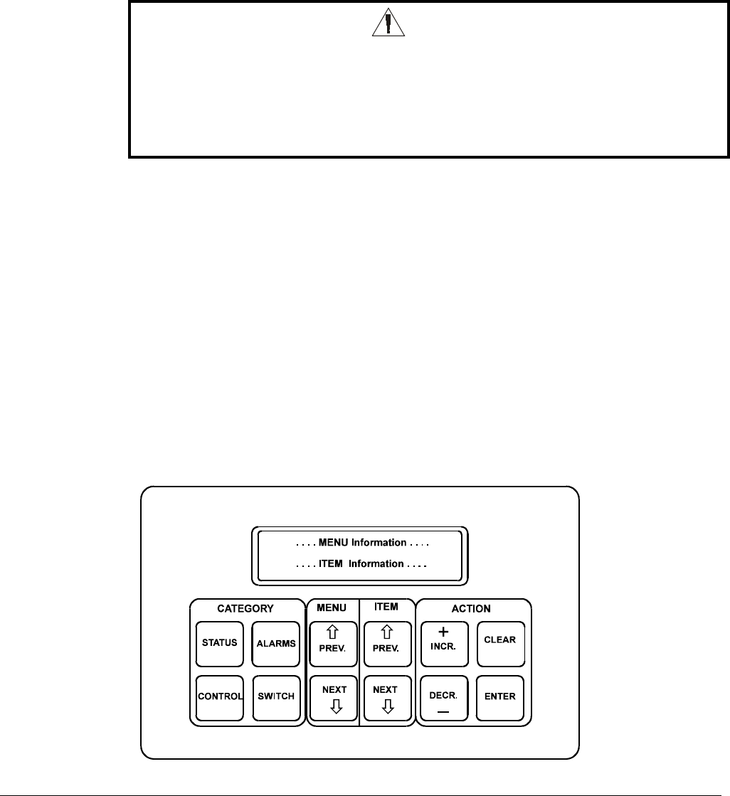
Keypad / Display
Figure 27, Keypad / Display