Unit installation
Table Of Contents
- Introduction
- Installation
- Physical Data
- Electrical Data
- Dimensional Data
- Startup
- Operation
- Global UNT Controller Installation and Operation
- General Description
- Optional Sensors
- Sensors and Transducers
- Control Wiring
- External Voltage Inputs
- Interlock Wiring
- Unit Set Points and Calibration
- Optional Sensors
- Field Wiring
- Power Wiring
- Power Supplies
- Analog input signals
- Digital input signals
- Remote Stop/Start
- Chilled Water Flow Switch
- Digital Outputs
- External Alarm Annunciator Circuitry
- PC Connection
- Software Identification
- Controller Inputs /Outputs
- Additional Global UNT Features
- Alarms
- Zone Terminal (Optional)
- Zone Terminal Glossary
- UNT Troubleshooting Chart
- MicroTech Controller Installation and Operation
- Sensors and transducers
- Control wiring
- Remote 4-20 milliamp signals
- Interlock wiring
- Unit set points and calibration
- Modem kit
- Lead-Lag
- Field Wiring
- Power Wiring
- Power Supplies
- Analog Input Signals
- Digital Input Signals
- Remote Stop/Start
- Chilled Water Flow Switch
- Digital Outputs
- Chilled Water Pump Relay
- External Alarm Annunciator Circuitry
- PC Connection
- Telephone line
- Software Identification
- Controller Inputs /Outputs
- Reset Options
- Soft Loading
- Manual Operation
- Compressor Staging
- Head Pressure Control
- Pumpdown Control
- Safety Systems
- Circuit Alarm Conditions
- System Alarm Conditions
- Sequence of Operation
- Start-Up and Shutdown
- Keypad / Display
- Menu Descriptions
- Trouble Analysis for the MicroTech
- Test Procedures
- Unit Maintenance
- Service

IOMM AGZ-3 AGZ 035A through 065A 57
Relay Board Outputs
All of the MicroTech panel outputs are controlled by solid-state relays which are driven by the model
250 controller. The controller activates a solid-state relay by sending a “trigger” signal to the output
board via the attached ribbon cable. The relay responds to the trigger by lowering its resistance which
allows current to flow through its “contacts”. When the controller removes the trigger signal, the
relay’s resistance becomes very high, causing the current flow to stop. The outputs are individually
protected by a 5 amp fuse mounted on the output board adjacent to each relay. Table 19 provides
additional information about each output. Refer to the MicroTech Staging schematic for digital
output wiring.
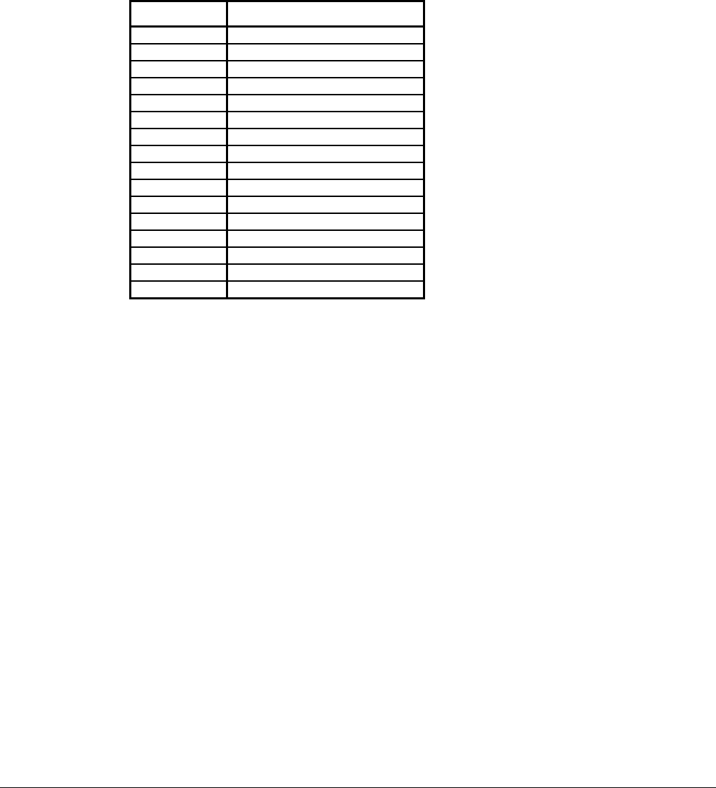
Table 19, Relay Board Outputs
Digital Output
Number
Output Description
0 Alarm Circuit
1 Chilled Water Pump Relay
2 Liquid Line Solenoid Circuit #1
3 Liquid Line Solenoid Circuit #2
4 Compressor #1 Circuit #1
5 Compressor #2 Circuit #2
6 Hot Gas Bypass Circuit #1
7 Hot Gas Bypass Circuit #2
8 Compressor #3 Circuit #1
9 Compressor #4 Circuit #2
10 Condenser Fan (M11)
11 Condenser Fan (M12)
12 Spare
13 Condenser Fan (M21)
14 Condenser Fan (M22)
15 Spare
Reset Options
User reset options are located in the “Leaving Water Setpoint” menu. The options are:
None
“None” is the default value and the leaving evaporator water temperature controls the unit.
Return
When selecting “Return” as the reset mode, the controller resets the leaving water temperature set
point as required to maintain the selected return water temperature.
4 - 20 ma (remote reset signal)
When selecting “4-20ma” as the reset mode, the controller will reset the leaving water temperature to
a higher value based on a percentage of the “Maximum Chilled Water Reset”. At 4ma or less, the
leaving water temperature is not reset. At 20ma the leaving water temperature is reset to the
maximum. Between 4 and 20 ma, the leaving water temperature is reset proportionally to the reset
input signal.
Outside Air
When selecting “Outside Air” as the reset mode, the controller will reset the leaving water
temperature to a higher value based on the temperature of the outside air (ambient). As the outside air
temperature decreases, the leaving water temperature is reset up until the maximum reset is obtained.
When the outside air temperature is above the outside air temperature reset setpoint the leaving water
temperature is not reset and is controlled to the leaving water temperature setpoint.


