
Unit installation


Table Of Contents
- Introduction
- Installation
- Physical Data
- Electrical Data
- Dimensional Data
- Startup
- Operation
- Global UNT Controller Installation and Operation
- General Description
- Optional Sensors
- Sensors and Transducers
- Control Wiring
- External Voltage Inputs
- Interlock Wiring
- Unit Set Points and Calibration
- Optional Sensors
- Field Wiring
- Power Wiring
- Power Supplies
- Analog input signals
- Digital input signals
- Remote Stop/Start
- Chilled Water Flow Switch
- Digital Outputs
- External Alarm Annunciator Circuitry
- PC Connection
- Software Identification
- Controller Inputs /Outputs
- Additional Global UNT Features
- Alarms
- Zone Terminal (Optional)
- Zone Terminal Glossary
- UNT Troubleshooting Chart
- MicroTech Controller Installation and Operation
- Sensors and transducers
- Control wiring
- Remote 4-20 milliamp signals
- Interlock wiring
- Unit set points and calibration
- Modem kit
- Lead-Lag
- Field Wiring
- Power Wiring
- Power Supplies
- Analog Input Signals
- Digital Input Signals
- Remote Stop/Start
- Chilled Water Flow Switch
- Digital Outputs
- Chilled Water Pump Relay
- External Alarm Annunciator Circuitry
- PC Connection
- Telephone line
- Software Identification
- Controller Inputs /Outputs
- Reset Options
- Soft Loading
- Manual Operation
- Compressor Staging
- Head Pressure Control
- Pumpdown Control
- Safety Systems
- Circuit Alarm Conditions
- System Alarm Conditions
- Sequence of Operation
- Start-Up and Shutdown
- Keypad / Display
- Menu Descriptions
- Trouble Analysis for the MicroTech
- Test Procedures
- Unit Maintenance
- Service
IOMM AGZ-3 AGZ 035A through 065A 47
DISPLAYS, SYMBOLS, KEYS, AND BUTTONS
The Zone Terminal simultaneously displays three set points or sensed values. In addition, flashing
symbols indicate when items are in a state of alarm. The keys, buttons, displays, and symbols are
explained below.
Table 15, Displays, Symbols, Keys, and Buttons
DISPLAYS, SYMBOLS,
KEYS, BUTTONS
DESCRIPTION
Display Button
1, 2, 3
Select the value you want to monitor or adjust.
Enter Key
Use to commit your changes. Adjustments are
not processed unless you press Enter.
Flashing Numbers
Appear in Display 1, 2, or 3 to indicate
numbers you can adjust. Numbers that do not
flash are monitor only numbers.
Flashing
s, m, ( | )
Shows an item is in alarm.
Mode Selector Button
Press this button to select Operating Modes:
Monitor, Adjust, Password, Time Scheduling.
A green Mode Indicator light moves through
the modes.
On/Off Status Symbols( | )
for On/a circle (m) for Off
Observe On/Off conditions of a point in the
HVAC controller with these symbols. A bar (| )
for On, a circle (m) for Off. These are always
monitor only items. If the symbol flashes, item
is in alarm.
Red Alarm Light
Flashes anytime a problem exists regardless
of which Operating Mode you have entered.
Up (↑) or Down (↓) Arrow
Keys
Use these keys to adjust a flashing number.
l
Appears in the displays, and corresponds to
the item you are monitoring or adjusting.
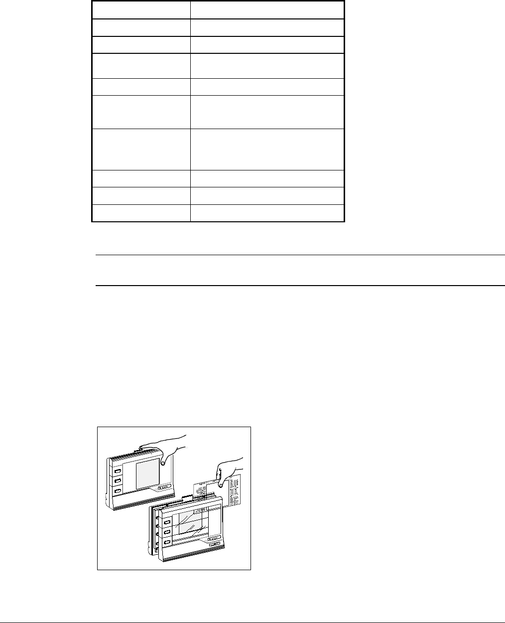
INSTALLING THE PLASTIC LABELS
Note: The insert is normally factory-installed. These steps are required only if the insert is
not already installed.
To use the ZT, you'll need the plastic label that is included with your ZT.
Insert
The clear plastic Insert is a custom-made label unique to your chiller. Use this Insert when
monitoring or adjusting specific items of your system:
1.
With the ZT on a flat surface, press the white tab with your index finger (Figure 25).
2.
Pull the front cover of the ZT away from the back and slide the Insert into position.
3.
Press the ZT together. With the Insert in place and the ZT connected, the l in the top position of
each display lines up with the first word.
Figure 25, Installing the Insert