
Unit installation


Table Of Contents
- Introduction
- Installation
- Physical Data
- Electrical Data
- Dimensional Data
- Startup
- Operation
- Global UNT Controller Installation and Operation
- General Description
- Optional Sensors
- Sensors and Transducers
- Control Wiring
- External Voltage Inputs
- Interlock Wiring
- Unit Set Points and Calibration
- Optional Sensors
- Field Wiring
- Power Wiring
- Power Supplies
- Analog input signals
- Digital input signals
- Remote Stop/Start
- Chilled Water Flow Switch
- Digital Outputs
- External Alarm Annunciator Circuitry
- PC Connection
- Software Identification
- Controller Inputs /Outputs
- Additional Global UNT Features
- Alarms
- Zone Terminal (Optional)
- Zone Terminal Glossary
- UNT Troubleshooting Chart
- MicroTech Controller Installation and Operation
- Sensors and transducers
- Control wiring
- Remote 4-20 milliamp signals
- Interlock wiring
- Unit set points and calibration
- Modem kit
- Lead-Lag
- Field Wiring
- Power Wiring
- Power Supplies
- Analog Input Signals
- Digital Input Signals
- Remote Stop/Start
- Chilled Water Flow Switch
- Digital Outputs
- Chilled Water Pump Relay
- External Alarm Annunciator Circuitry
- PC Connection
- Telephone line
- Software Identification
- Controller Inputs /Outputs
- Reset Options
- Soft Loading
- Manual Operation
- Compressor Staging
- Head Pressure Control
- Pumpdown Control
- Safety Systems
- Circuit Alarm Conditions
- System Alarm Conditions
- Sequence of Operation
- Start-Up and Shutdown
- Keypad / Display
- Menu Descriptions
- Trouble Analysis for the MicroTech
- Test Procedures
- Unit Maintenance
- Service
IOMM AGZ-3 AGZ 035A through 065A 41
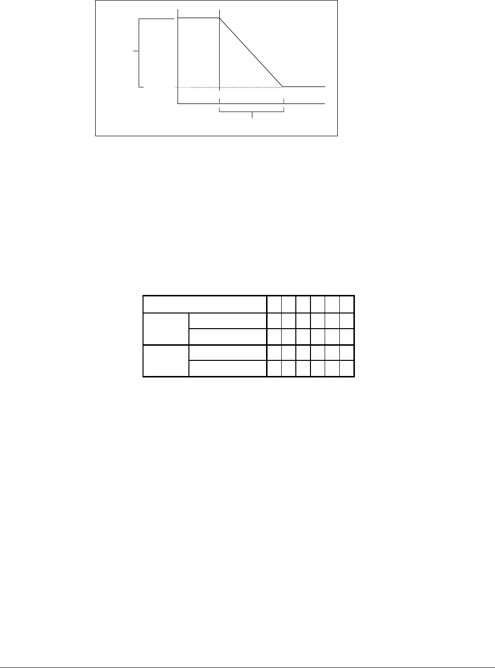
Figure 21, Zone Temperature Reset
LWRB
LWSP
ZTLL ZTHL
ZTRB
(ZTLL=ZTHL - ZTRB)
As the Zone Temperature increases above the Zone Temperature Low Limit (ZTLL), the controller
decreases the Actual Leaving Water Setpoint from its Leaving High Limit (Leaving Water Setpoint
plus Leaving Reset Band) to the Leaving Water Setpoint. When the Zone Temperature reaches the
ZTHL, the Actual Leaving Water Setpoint equals the Leaving Water Setpoint (AI-4). If the Zone
Temperature sensor is missing or unreliable, no reset occurs and the Actual Leaving Water Setpoint
equals the Leaving Water Setpoint. If the Leaving Water Sensor (AI-1) becomes unreliable, the
compressor command is forced to 0%.
The Zone Terminal is required to activate and change the reset values.
Figure 22, RESET DIP SWITCH CONFIGURATION
OUTSIDE AIR / RETURN WATER / ZONE TEMPERATURE
Switch 123456
On (10V) X X X X
SW2
Off (2V) X X
On (T) X X
SW1
Off (V) X X X X
Remote Reset (2 to 10VDC input)
When selected, a 2 to 10Vdc signal is connected to TB-7 terminals #134 and #135. This input can be
achieved by using a 4-20ma signal and conditioning it with a 500 ohm resistor. This input resets the
leaving water temperature to a higher value based on the reset input signal magnitude. At a 2Vdc
(4ma) chiller signal input, the controller uses the Setpoint Dial setting. At a 10Vdc (20ma) signal
input, the controller adds the reset value to the Dial Setpoint for the controlling temperature.
Between 2Vdc and 10Vdc, a proportional value is added to the Dial Setpoint for the controlling
temperature. The leaving water temperature can be reset upwards an additional 15
o
F. The Zone
Terminal is required to change the reset values.
Demand Limit (0 to 10VDC input)
When selected, a 0 to 10Vdc signal is connected to TB-7 terminals #134 and #135. This input limits
the cooling capacity (0 to 100%). At 0Vdc signal input, the controller does not limit compressor
staging. At 10Vdc signal input, the chiller would be off. Between 0Vdc and 10Vdc, a proportional
percentage capacity is available.