
Unit installation


Table Of Contents
- Introduction
- Installation
- Physical Data
- Electrical Data
- Dimensional Data
- Startup
- Operation
- Global UNT Controller Installation and Operation
- General Description
- Optional Sensors
- Sensors and Transducers
- Control Wiring
- External Voltage Inputs
- Interlock Wiring
- Unit Set Points and Calibration
- Optional Sensors
- Field Wiring
- Power Wiring
- Power Supplies
- Analog input signals
- Digital input signals
- Remote Stop/Start
- Chilled Water Flow Switch
- Digital Outputs
- External Alarm Annunciator Circuitry
- PC Connection
- Software Identification
- Controller Inputs /Outputs
- Additional Global UNT Features
- Alarms
- Zone Terminal (Optional)
- Zone Terminal Glossary
- UNT Troubleshooting Chart
- MicroTech Controller Installation and Operation
- Sensors and transducers
- Control wiring
- Remote 4-20 milliamp signals
- Interlock wiring
- Unit set points and calibration
- Modem kit
- Lead-Lag
- Field Wiring
- Power Wiring
- Power Supplies
- Analog Input Signals
- Digital Input Signals
- Remote Stop/Start
- Chilled Water Flow Switch
- Digital Outputs
- Chilled Water Pump Relay
- External Alarm Annunciator Circuitry
- PC Connection
- Telephone line
- Software Identification
- Controller Inputs /Outputs
- Reset Options
- Soft Loading
- Manual Operation
- Compressor Staging
- Head Pressure Control
- Pumpdown Control
- Safety Systems
- Circuit Alarm Conditions
- System Alarm Conditions
- Sequence of Operation
- Start-Up and Shutdown
- Keypad / Display
- Menu Descriptions
- Trouble Analysis for the MicroTech
- Test Procedures
- Unit Maintenance
- Service
4 AGZ 035A through 065A IOMM AGZ-3
Installation
Note: Installation is to be performed by qualified personnel who are familiar with local codes
and regulations.
WARNING
Sharp edges on unit and coil surfaces are a potential hazard to personal
safety. Avoid contact with them.
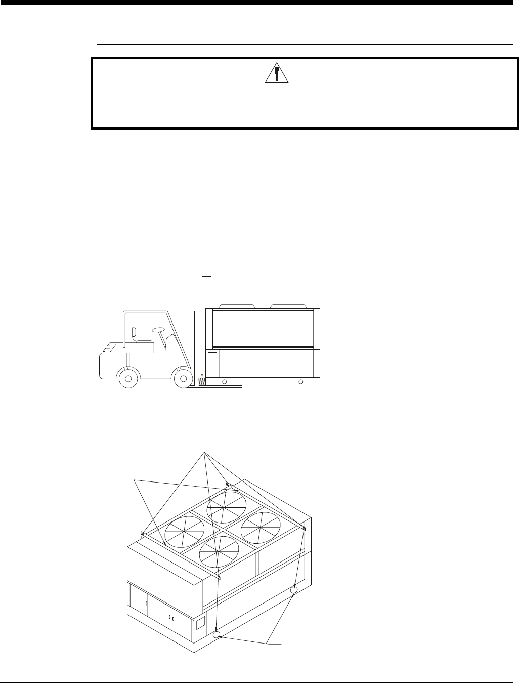
Handling
Be careful to avoid rough handling of the unit. Do not push or pull the unit from anything other than
the base. Block the pushing vehicle away from the unit to prevent damage to the sheet metal cabinet
and end frame (see Figure 1).
To lift the unit, 2 1/2" (64mm) diameter lifting holes are provided in the base of the unit. Arrange
spreader bars and cables to prevent damage to the condenser coils or cabinet (see Figure 2).
Figure 1, Suggested Pushing Arrangement
Figure 2, Suggested Lifting Arrangement
These rigging holes
must be used.
Spreader Bars
recommended
(use caution)
Number of fans may vary
from this diagram. The
lifting method will remain
the same
Blocking is required
across full width