
Unit installation


Table Of Contents
- Introduction
- Installation
- Physical Data
- Electrical Data
- Dimensional Data
- Startup
- Operation
- Global UNT Controller Installation and Operation
- General Description
- Optional Sensors
- Sensors and Transducers
- Control Wiring
- External Voltage Inputs
- Interlock Wiring
- Unit Set Points and Calibration
- Optional Sensors
- Field Wiring
- Power Wiring
- Power Supplies
- Analog input signals
- Digital input signals
- Remote Stop/Start
- Chilled Water Flow Switch
- Digital Outputs
- External Alarm Annunciator Circuitry
- PC Connection
- Software Identification
- Controller Inputs /Outputs
- Additional Global UNT Features
- Alarms
- Zone Terminal (Optional)
- Zone Terminal Glossary
- UNT Troubleshooting Chart
- MicroTech Controller Installation and Operation
- Sensors and transducers
- Control wiring
- Remote 4-20 milliamp signals
- Interlock wiring
- Unit set points and calibration
- Modem kit
- Lead-Lag
- Field Wiring
- Power Wiring
- Power Supplies
- Analog Input Signals
- Digital Input Signals
- Remote Stop/Start
- Chilled Water Flow Switch
- Digital Outputs
- Chilled Water Pump Relay
- External Alarm Annunciator Circuitry
- PC Connection
- Telephone line
- Software Identification
- Controller Inputs /Outputs
- Reset Options
- Soft Loading
- Manual Operation
- Compressor Staging
- Head Pressure Control
- Pumpdown Control
- Safety Systems
- Circuit Alarm Conditions
- System Alarm Conditions
- Sequence of Operation
- Start-Up and Shutdown
- Keypad / Display
- Menu Descriptions
- Trouble Analysis for the MicroTech
- Test Procedures
- Unit Maintenance
- Service
16 AGZ 035A through 065A IOMM AGZ-3
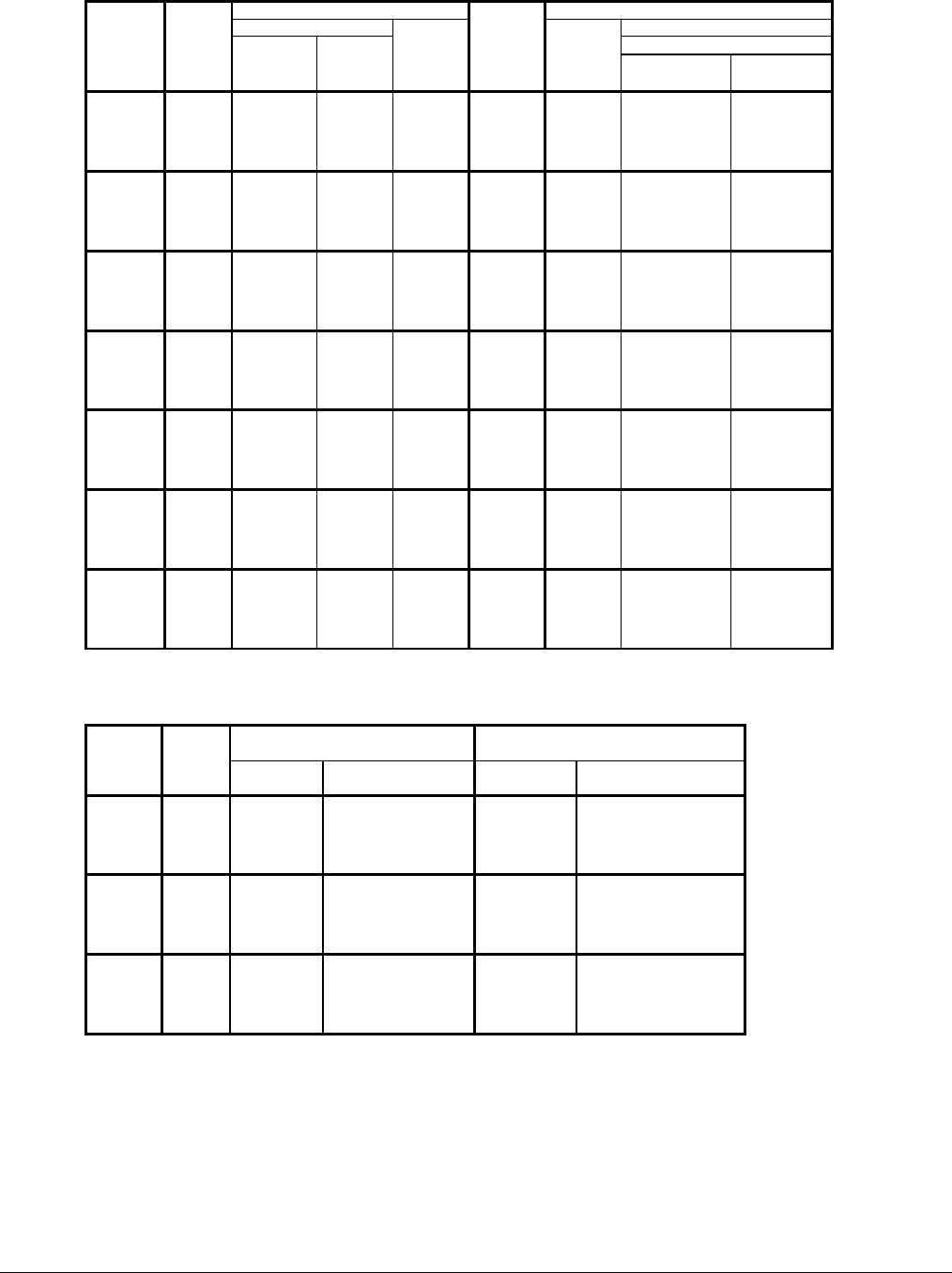
Table 10, AGZ 035A - 065A, 60 Hz, Compressor and Condenser Fan Motor Amp Draw
Rated Load Amps Locked Rotor Amps
Compressors Compressors
Across-The-Line
AGZ
Unit
Size
Volts
No.
1 & 3
(Each)
No.
2 & 4
(Each)
Fan
Motors
(Each)
No. Of
Fan
Motors
Fan
Motors
(Each)
No.1 & 3
(Each)
No.2 & 4
(Each)
208 30.5 30.5 4.0 4 17.0 232 232
230 30.5 30.5 4.0 4 17.0 232 232
380 18.6 18.6 3.4 4 14.4 144 144
460 15.8 15.8 2.0 4 8.5 125 125
035A
575 11.6 11.6 2.2 4 10.3 100 100
208 35.2 35.2 4.0 4 17.0 278 278
230 35.2 35.2 4.0 4 17.0 278 278
380 22.8 22.8 3.4 4 14.4 151 151
460 16.5 16.5 2.0 4 8.5 127 127
040A
575 13.7 13.7 2.2 4 10.3 100 100
208 35.2 41.5 5.8 4 23.7 278 350
230 35.2 41.5 5.8 4 23.7 278 350
380 22.8 28.0 3.4 4 14.4 151 195
460 16.5 21.8 2.8 4 10.7 127 158
045A
575 13.7 17.3 2.3 4 11.5 100 125
208 41.5 41.5 5.8 4 23.7 350 350
230 41.5 41.5 5.8 4 23.7 350 350
380 28.0 28.0 3.4 4 14.4 195 195
460 21.8 21.8 2.8 4 10.7 158 158
050A
575 17.3 17.3 2.3 4 11.5 125 125
208 41.5 52.8 5.8 4 23.7 350 425
230 41.5 52.8 5.8 4 23.7 350 425
380 28.0 32.7 3.4 4 14.4 195 239
460 21.8 23.7 2.8 4 10.7 158 187
055A
575 17.3 22.1 2.3 4 11.5 125 148
208 52.8 52.8 5.8 4 23.7 425 425
230 52.8 52.8 5.8 4 23.7 425 425
380 32.7 32.7 3.4 4 14.4 239 239
460 23.7 23.7 2.8 4 10.7 187 187
060A
575 22.1 22.1 2.3 4 11.5 148 148
208 52.8 52.8 5.8 4 23.7 425 425
230 52.8 52.8 5.8 4 23.7 425 425
380 32.7 32.7 3.4 4 14.4 239 239
460 23.7 23.7 2.8 4 10.7 187 187
065A
575 22.1 22.1 2.3 4 11.5 148 148
Table 11, AGZ035A - 065A, 60 Hz Single Point Power, Field Wiring Data
Wiring to Standard
Power Block
Wiring to Optional
Non-Fused Disconnect Switch
AGZ
Unit
Size
Volts
Terminal
Amps
Connector Wire Range
(Copper Wire Only)
Terminal
Amps
Connector Wire Range
(Copper Wire Only)
208 335 # 4 - 400 MCM 225 #4 – 4/0
230 335 # 4 - 400 MCM 225 #4 – 4/0
380 175 #12 - 2/0 100 #14 - 1/0
460 175 #12 - 2/0 100 #14 - 1/0
035A
575 175 #12 - 2/0 100 #14 - 1/0
208 335 # 4 - 400 MCM 225 #4 – 4/0
230 335 # 4 - 400 MCM 225 #4 – 4/0
380 175 #12 - 2/0 150 #4 – 4/0
460 175 #12 - 2/0 100 #14 - 1/0
040A
575 175 #12 - 2/0 100 #14 - 1/0
208 335 # 4 - 400 MCM 225 #4 – 4/0
230 335 # 4 - 400 MCM 225 #4 – 4/0
380 175 #12 - 2/0 150 #4 – 4/0
460 175 #12 - 2/0 100 #14 - 1/0
045A
575 175 #12 - 2/0 100 #14 - 1/0
Table continued on next page