
Unit installation


Table Of Contents
- Introduction
- Installation
- Physical Data
- Electrical Data
- Dimensional Data
- Startup
- Operation
- Global UNT Controller Installation and Operation
- General Description
- Optional Sensors
- Sensors and Transducers
- Control Wiring
- External Voltage Inputs
- Interlock Wiring
- Unit Set Points and Calibration
- Optional Sensors
- Field Wiring
- Power Wiring
- Power Supplies
- Analog input signals
- Digital input signals
- Remote Stop/Start
- Chilled Water Flow Switch
- Digital Outputs
- External Alarm Annunciator Circuitry
- PC Connection
- Software Identification
- Controller Inputs /Outputs
- Additional Global UNT Features
- Alarms
- Zone Terminal (Optional)
- Zone Terminal Glossary
- UNT Troubleshooting Chart
- MicroTech Controller Installation and Operation
- Sensors and transducers
- Control wiring
- Remote 4-20 milliamp signals
- Interlock wiring
- Unit set points and calibration
- Modem kit
- Lead-Lag
- Field Wiring
- Power Wiring
- Power Supplies
- Analog Input Signals
- Digital Input Signals
- Remote Stop/Start
- Chilled Water Flow Switch
- Digital Outputs
- Chilled Water Pump Relay
- External Alarm Annunciator Circuitry
- PC Connection
- Telephone line
- Software Identification
- Controller Inputs /Outputs
- Reset Options
- Soft Loading
- Manual Operation
- Compressor Staging
- Head Pressure Control
- Pumpdown Control
- Safety Systems
- Circuit Alarm Conditions
- System Alarm Conditions
- Sequence of Operation
- Start-Up and Shutdown
- Keypad / Display
- Menu Descriptions
- Trouble Analysis for the MicroTech
- Test Procedures
- Unit Maintenance
- Service
12 AGZ 035A through 065A IOMM AGZ-3
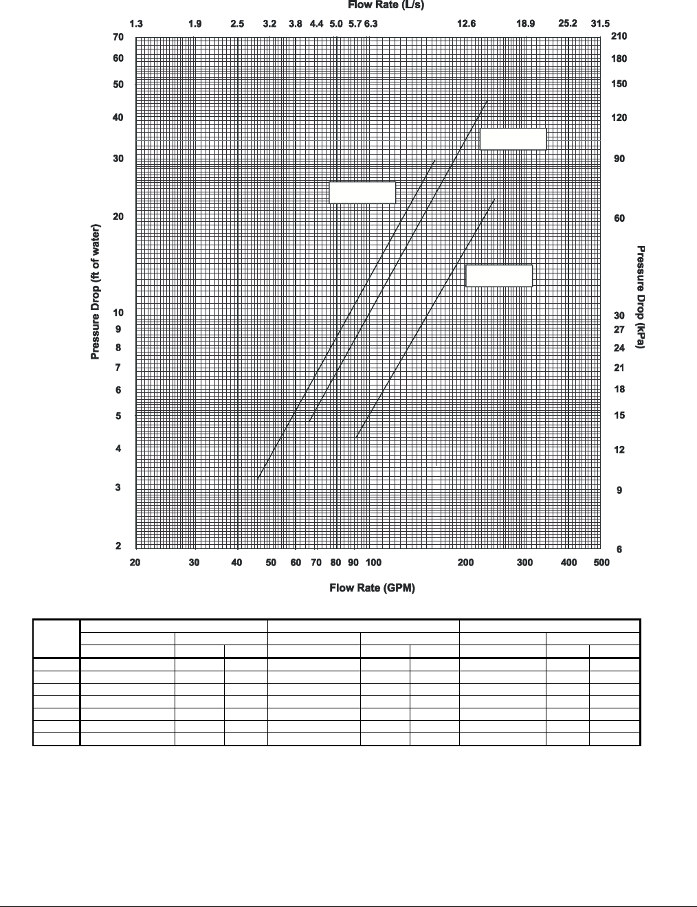
Figure 7, Pressure Drop Curve
03 A-040A
04
A
-060A
06
A
5
5
5
NOMINAL MAXIMUM MINIMUM
Pressure Drop Flow Pressure Drop Flow Pressure Drop Flow
AGZ
Unit
Size
(ft) of Water (gpm) (lps) (ft) of Water (gpm) (lps) (ft) of Water (gpm) (lps)
035AS 9.2 82 5.17 23.1 137 8.62 3.9 51 3.23
040AS 11.5 93 5.87 28.8 155 9.78 4.9 58 3.67
045AS 11.2 106 6.69 28.2 177 11.15 4.8 66 4.18
050AS 13.4 117 7.38 33.6 195 12.30 5.7 73 4.61
055AS 16.2 129 8.14 40.0 215 13.56 7.0 81 5.09
060AS 18.0 138 8.71 45.0 230 14.51 7.7 86 5.44
065AS 10.0 146 9.21 25.1 243 15.35 4.3 91 5.76
Minimum and maximum flows are established to ensure the Delta-T for each unit size falls within the 6 - 16°F range for proper unit control.