
Unit installation


Table Of Contents
- Introduction
- Installation
- Physical Data
- Electrical Data
- Dimensional Data
- Startup
- Operation
- Global UNT Controller Installation and Operation
- General Description
- Optional Sensors
- Sensors and Transducers
- Control Wiring
- External Voltage Inputs
- Interlock Wiring
- Unit Set Points and Calibration
- Optional Sensors
- Field Wiring
- Power Wiring
- Power Supplies
- Analog input signals
- Digital input signals
- Remote Stop/Start
- Chilled Water Flow Switch
- Digital Outputs
- External Alarm Annunciator Circuitry
- PC Connection
- Software Identification
- Controller Inputs /Outputs
- Additional Global UNT Features
- Alarms
- Zone Terminal (Optional)
- Zone Terminal Glossary
- UNT Troubleshooting Chart
- MicroTech Controller Installation and Operation
- Sensors and transducers
- Control wiring
- Remote 4-20 milliamp signals
- Interlock wiring
- Unit set points and calibration
- Modem kit
- Lead-Lag
- Field Wiring
- Power Wiring
- Power Supplies
- Analog Input Signals
- Digital Input Signals
- Remote Stop/Start
- Chilled Water Flow Switch
- Digital Outputs
- Chilled Water Pump Relay
- External Alarm Annunciator Circuitry
- PC Connection
- Telephone line
- Software Identification
- Controller Inputs /Outputs
- Reset Options
- Soft Loading
- Manual Operation
- Compressor Staging
- Head Pressure Control
- Pumpdown Control
- Safety Systems
- Circuit Alarm Conditions
- System Alarm Conditions
- Sequence of Operation
- Start-Up and Shutdown
- Keypad / Display
- Menu Descriptions
- Trouble Analysis for the MicroTech
- Test Procedures
- Unit Maintenance
- Service
IOMM AGZ-3 AGZ 035A through 065A 11
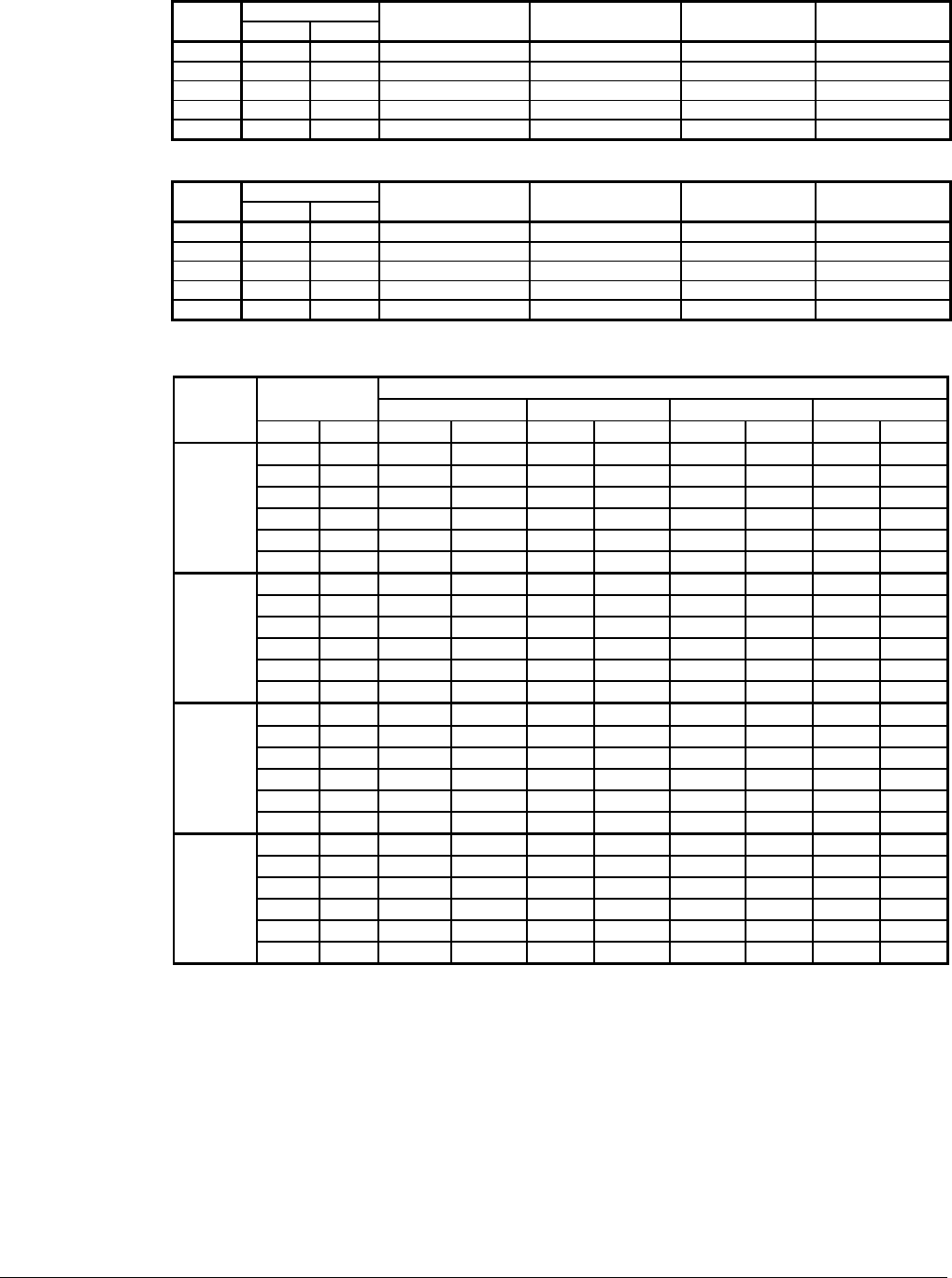
Table 4, Ethylene Glycol Correction Factors
Freeze Point
%
E.G.
°F °C
Capacity Power Flow Pressure Drop
10
26 -3 0.991 0.996 1.013 1.070
20
18 -8 0.982 0.992 1.040 1.129
30
7 -14 0.972 0.986 1.074 1.181
40
-7 -22 0.961 0.976 1.121 1.263
50
-28 -33 0.946 0.966 1.178 1.308
Table 5, Propylene Glycol Correction Factors
Freeze Point
%
P.G.
°F °C
Capacity Power Flow Pressure Drop
10
26 -3 0.987 0.992 1.010 1.068
20
19 -7 0.975 0.985 1.028 1.147
30
9 -13 0.962 0.978 1.050 1.248
40
-5 -21 0.946 0.971 1.078 1.366
50
-27 -33 0.929 0.965 1.116 1.481
Table 6, Capacity and Power Derates
Fouling Factor
Chilled Water
Delta-T
0.0001 (0.0176) 0.00025 (0.044) 0.00075 (0.132) 0.00175 (0.308)
ALTITUDE
°F °C Cap. Power Cap. Power Cap. Power Cap. Power
6 3.3 0.992 0.995 0.985 0.993 0.962 0.986 0.919 0.972
8 4.4 0.995 0.997 0.988 0.995 0.965 0.988 0.922 0.974
10 5.6 1.000 1.000 0.993 0.998 0.970 0.991 0.927 0.977
12 6.7 1.005 1.002 0.998 1.000 0.975 0.993 0.932 0.979
14 6.8 1.010 1.005 1.003 1.003 0.980 0.996 0.936 0.982
SEA
LEVEL
16 8.9 1.014 1.007 1.007 1.005 0.984 0.998 0.940 0.984
6 3.3 0.978 1.005 0.971 1.003 0.949 0.996 0.906 0.982
8 4.4 0.982 1.007 0.975 1.005 0.953 0.998 0.910 0.984
10 5.6 0.986 1.009 0.979 1.007 0.956 1.000 0.914 0.986
12 6.7 0.992 1.011 0.985 1.009 0.962 1.002 0.919 0.988
14 6.8 0.997 1.014 0.990 1.012 0.967 1.005 0.924 0.991
2000 feet
(610 m)
16 8.9 1.000 1.016 0.993 1.014 0.970 1.007 0.927 0.993
6 3.3 0.966 1.016 0.959 1.014 0.937 1.007 0.895 0.993
8 4.4 0.969 1.018 0.962 1.016 0.940 1.009 0.898 0.995
10 5.6 0.973 1.021 0.966 1.019 0.944 1.012 0.902 0.998
12 6.7 0.978 1.025 0.971 1.023 0.949 1.016 0.906 1.002
14 6.8 0.982 1.027 0.975 1.025 0.953 1.018 0.910 1.004
4000 feet
(1220 m)
16 8.9 0.986 1.028 0.979 1.026 0.956 1.019 0.914 1.005
6 3.3 0.953 1.025 0.946 1.023 0.924 1.016 0.883 1.002
8 4.4 0.955 1.028 0.948 1.026 0.926 1.019 0.885 1.005
10 5.6 0.959 1.031 0.952 1.029 0.930 1.022 0.889 1.008
12 6.7 0.963 1.034 0.956 1.032 0.934 1.024 0.893 1.011
14 6.8 0.968 1.036 0.961 1.034 0.939 1.026 0.897 1.013
6000 feet
(1830 m)
16 8.9 0.972 1.037 0.965 1.035 0.943 1.027 0.901 1.014
Evaporator Flow and Pressure Drop
Evaporator flow rate must fall between the minimum and maximum values shown in the evaporator
pressure drop table on Figure 7.
Measure the chilled water pressure drop through the evaporator at factory installed pressure taps. It is
important not to include the effect of valves or strainers in these readings.
Varying chilled water flow through the evaporator while the compressor(s) are operating is not
recommended.