
Operating instructions


68 IMM AGSB-60
the high pressure switch will close again at 200 psig (1379 kPa), the control circuit will remain
locked out and it must be reset through the MicroTech II control.
The control is mounted in the control panel.
Compressor motor protection
The compressors are supplied with two types of motor protection. Solid state electronic
overloads mounted in the control box sense motor current to within 2% of the operating amps.
The MUST TRIP amps are equal to 140% of unit nameplate compressor RLA. The MUST
HOLD amps are equal to 125% of unit nameplate RLA. A trip of these overloads can result
from the unit operating outside of normal conditions. Repeat overload trips under normal
operation can indicate wiring or compressor motor problems. The overloads are manual reset
and must be reset at the overload as well as through the MicroTech II controller.
The compressors also have a solid state Guardistor£ circuit that provides motor over
temperature protection. The Guardistor£ circuit has automatic reset and gives a Starter Fault
(F75) that is cleared through the starter display and must also be reset through the MicroTech
II control.
Head pressure control
The compressor must be running in order to stage its fans on.
Condenser pressure trim control is accomplished using a variable frequency drive (VFD) on
the first two fans that turn on. This VFD control uses a proportional integral function to drive
the saturated condenser temperature to a target value by changing the fan speed. The target
value is normally the same as the saturated condenser temperature target setpoint.
The VFD will start the fans when the saturated condenser temperature goes above the
temperature target. Once the VFD fans are on, they will not shut off until the saturated
condenser temperature is less than the minimum saturated temperature plus 5 degrees F
(2.7 degrees C).
Stage up Compensation
In order to create a smoother transition when another fan is staged on, the VFD compensates
by slowing down initially. This is accomplished by adding the new fan stage up deadband to
the VFD target. The higher target causes the VFD logic to decrease fan speed. Then, every 10
seconds, 0.5 degrees F (0.25 degrees C) is subtracted from the VFD target until it is equal to
the saturated condenser temperature target setpoint. This will allow the VFD to slowly bring
the saturated condenser temperature back down.
Condenser Target
This logic is only used with VFD = Yes in the controller set point screen. Most applications
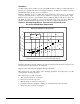
will benefit from using the factory default values. The AGSU30101F software version has two
setpoints used to set a minimum(Min) and a maximum(Max) range for the saturated condenser
target. This can be found on the circuit controller at Set Fan Sps(5). This allows for a floating
condenser target based on saturated evaporator temperature. The default values of the
minimum and maximum are both set to 110°F (43.3°C) saturated condensing temperature. This
will normally provide the most stable unit operation. Adjusting the Min or Max setpoint at
each circuit controller will vary the condenser target along a line determined by two points
which are; 1) 85°F (29.4C) saturated condenser and 20°F (6.7°C) saturated suction, and 2)
110°F (43.3°C) saturated condenser and 50°F (10.0°C) saturated suction. Note that the chiller
system is designed for specific refrigerant flow capacities, which may be exceeded by
decreasing the condenser target. The result will be at lower ambient temperatures, the chiller
may attain the maximum unit tonnage capacities while compressor loading will be limited on
low discharge superheat.
Fan Stages with VFD Option
The VFD option must always be enabled. The first two fans are controlled by the fan VFD.
This leaves 6 stages of fan control available with 8 fan circuits, and 4 stages available on 6 fan