
Operating instructions


IMM AGSB-60 67
Evaporator entering water temperature - This sensor is located on the evaporator water
inlet connection and is used for monitoring purposes and return water temperature reset
control.
Evaporator pressure transducer circuit #1, 2 (and 3) - This sensor is located on the suction
side of the compressor and is used to determine saturated suction refrigerant pressure and
temperature. It also provides low pressure freeze protection.
Condenser pressure transducer circuit #1, 2 (and 3) - the sensor is located on the discharge
of the oil separator and is used to read pressure and saturated refrigerant temperature. The
transducer will unload the compressor if a rise in head pressure occurs which is outside the
MicroTech II controller setpoint limits. The signal is also used in the calculation of discharge
superheat.
Liquid pressure transducer #1, 2 (and 3) – located on the liquid line ahead of the EXV. It is
used to determine liquid pressure and subcooling and is used to control the EXV.
Outside air - This sensor is located on the back of the control box on compressor #1 side. It
measures the outside air temperature, is used to determine if low ambient start logic is
necessary and can be the reference for low ambient temperature lockout.
Suction temperature circuit #1, 2, (and 3) - The sensor is located in a well on the suction
line. The purpose of the sensor is to measure refrigerant temperature and superheat.
Discharge line temperature circuit #1, 2 (and 3) - The sensor is located in a well on the
discharge line. It measures the refrigerant temperature and is used to calculate discharge
superheat.
Demand limit - This requires a field connection of a 4-20 milliamp DC signal from a building
automation system. It will determine the maximum number of cooling stages that can be
energized.
Evaporator water temperature reset - This requires a 4-20 milliamp DC signal from a
building automation system or temperature transmitter to reset the leaving chilled water
setpoint.
High condenser pressure control
The MicroTech II is equipped with a transducer in the high pressure side of each refrigerant
circuit. This pressure value is converted to saturated condenser temperature for condenser fan
staging and for limiting compressor capacity to keep the circuit within safe operating
conditions. For a detailed description of condenser fan logic, see the unit operating manual,
AGS OM-4 or later revision.
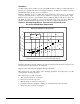
The high condenser pressure control operates according to a maximum allowable operating
condenser pressure curve which is based on the saturated evaporator temperature(see the AGS
OM for details). The circuit controller will display the calculated max saturated condenser
temperature “MaxCondSatT” on the View Refrigerant (6) screen. At 5 degrees F (2.7 degrees
C) saturated condenser temperature below the MaxCondSatT value, the chiller will be in a
hold condition and will not allow the compressor to load up. At 3 degrees F (1.6 degrees C)
below the MaxCondSatT the compressor will begin to unload to reduce the condenser
pressure.
If the saturated condenser temperature exceeds the MaxCondSatT, it will shut down the
compressor with no pumpdown and go into an OFF: Alarm state. At the time of the alarm the
circuit data will be recorded in the Alarm buffer.
Mechanical high pressure equipment protection control
The high pressure equipment protection control is a single pole, pressure-activated switch that
opens on a pressure rise. When the switch opens, the control circuit is de-energized, dropping
power to the compressor and fan motor contactors. The switch is factory set (non-adjustable)
to open at 310 psig (2137 kPa) ±7 psig and reclose at 200 psig (1379 kPa) ±7 psig. Although