
Operating instructions


58 IMM AGSB-60
Electrical Terminals
DANGER
Electric shock hazard and risk of personal injury or death exists. Turn off all
power before continuing with following service.
Periodically check electrical terminals for tightness and tighten as required.
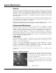
Condensers
The condensers are air-cooled and constructed of 3/8" (9.5mm) OD internally finned copper
tubes bonded in a staggered pattern into louvered aluminum (standard material) fins. No
maintenance is ordinarily required except the routine removal of dirt and debris from the
outside surface of the fins. McQuay recommends the use of foaming coil cleaners available at
most air conditioning supply outlets.
WARNING
Use caution when applying such coil cleaners as they can contain potentially
harmful chemicals. Breathing apparatus and protective clothing should be
worn. Thoroughly rinse all surfaces to remove any cleaner residue. Care
should be taken not to damage the fins during cleaning.
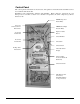
If the service technician has reason to believe that the refrigerant circuit contains
noncondensables, recovery of the noncondensables can be required, strictly following Clean
Air Act regulations governing refrigerant discharge to the atmosphere. The service Schrader
valves are located on both vertical coil headers on both sides of the unit at the control box end
of the coil. Access panels are located at the end of the condenser coil directly behind the
control panel. Recover the noncondensables with the unit off, after shutdown of 15 minutes or
longer, to allow air to collect at the top of the coil. Restart and run the unit for a brief period.
If necessary, shut the unit off and repeat the procedure. Follow accepted environmentally
sound practices when removing refrigerant from the unit.
Liquid Line Sight Glass
The AGS-B chiller electronic expansion valve, under normal operation, is controlled by
maintaining a calculated liquid line subcooling value. The EXV control, if the circuit is in
subcooling control, will vary the subcooling from 2 to 20 degrees F (1 to 11 degrees C) or
greater, depending upon operating conditions. If the circuit is operating in subcool control, the
liquid line sight glasses will not be an indication of charge amount. This is due to the chiller
controlling the liquid subcooling at that location. Calibration of the liquid line pressure
transducer and thermistor is required for proper control. An improper calibration may cause
the liquid line sight glass to flash due to false subcooling calculation.
On startup and during other operating conditions such as high LWT and ICE mode, the
expansion valve control will be in pressure control. If the circuit is in pressure control, a
flashing liquid line sight glass may be an indication of low refrigerant. The chiller will not go
to subcooling control if the subcooling is not equal to the calculated subcooling target for the
operating conditions while in pressure control. A flashing sight glass, while in pressure
control, may indicate excessive pressure drop in the liquid line, possibly due to a clogged
filter-drier or a restriction elsewhere in the liquid line (see Table 31 on page 61 for maximum
allowable pressure drops).