
Operating instructions

IMM AGSB-60 5
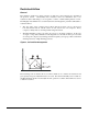
Location
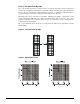
Locate the unit to provide proper airflow to the condenser. (See Figure 2 on page 6 for
required clearances).
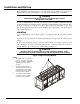
Due to the shape of the condenser coils on the AGS chillers, orient the unit so that prevailing
winds blow parallel to the unit length, thus minimizing the wind effect on condensing pressure
and performance. If low ambient temperature operation is expected, it is recommended that
optional wind baffles or louvers be field installed if the unit has no protection against
prevailing winds.
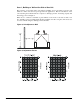
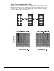
Using less clearance than shown in Figure 2 can cause discharge air recirculation to the
condenser and could have a significant detrimental effect on unit performance.
See Restricted Airflow beginning on page 7 for further information.
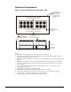
Service Access
Compressors, filter-driers, and manual liquid line shutoff valves are accessible on each side of
the unit adjacent to the control box. The evaporator heaters are located in each head.
Each compressor (two or three depending on unit size) has its own duplex control panel
located on the sides of the chiller between condenser coil sections. A control panel is to the
left of the condenser and compressor it controls. The outer control box contains the circuit
microprocessor. The box for circuit #1 also contains the unit microprocessor controller. The
solid state compressor starter, fan control and other power equipment are located in the inner
panel.
The side clearance required for airflow provides sufficient service clearance.
On all AGS units the condenser fans and motors can be removed from the top of the unit. The
complete fan/motor assembly can be removed for service. The fan must be removed for access
to wiring terminals at the top of the motor.
WARNING
Disconnect all power to the unit while servicing condenser fan motors or compressors.
Failure to do so can cause bodily injury or death.
Do not block access to the sides or ends of the unit with piping or conduit. These areas must
be open for service access. Do not block any access to the control panels with a field-mounted
disconnect switches. In particular, be sure that the power conduit to each panel does not
interfere with access to the filter-driers located on the unit base under the panels.