
Operating instructions

46 IMM AGSB-60
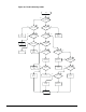
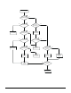
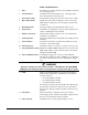
FLOW CHART DETAILS:
1. Fuses Determine if power line fuses have been installed, and if they
are operating properly.
2. Circuit Breaker Determine if the circuit breaker is off, or has tripped and
disconnected the line from the starter.
3. Power Line Voltage Verify that line voltage is present, and is the correct voltage.
4. Phase Order Fault If Fault Codes F1 or F2 are displayed on the control card
LED display, exchange any two incoming power line cable
connections.
5. Heat Sink Switch Investigate whether heat sink thermal switch is open.
6. Safety Device Determine if an equipment protection device attached to the
starter is disabling the start command.
7. Wiring Connections Verify that the wiring connections are correct and that the
terminations are tightened.
8. Air Temperature Investigate whether the air temperature surrounding the heat
sink is hot.
9. Air Circulation Determine if the airflow around the heat sink fins is being
restricted, or if a fan has failed.
10. Motor Overload Determine if the motor’s load is too large for the motor size.
11. Current Imbalance Fault If Fault Codes F23 or F24 are displayed on the control card
LED display, diagnose and correct the cause of the current
imbalance parameter P16.
12. Motor Winding Problem Conducting a megger test of the motor can identify an
internal motor winding problem. NOTE: To avoid damaging
the starter isolate the motor before conducting the megger
test.
WARNING
Hazardous voltages exist at the starter terminals. LOCK OUT ALL OF THE POWER
SOURCES before making resistance measurements to avoid personal injury or death.
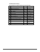
13. SCRs This step can help determine if a problem exists with the
SCRs. Using a multi-meter or similar device, measure the
resistance between:
• L1 terminal and T1 terminal
•
L2 terminal and T2 terminal
•
L3 terminal and T3 terminal
The resistance should be more than 50k ohms. Measure the
gate resistance between the white and red of each twisted
pair (6 total). The gate resistance should be between 8 and
50 ohms
.
14. Gate Pulses
This step can help to determine if the control card is
functioning properly. Check for gate firing voltage between
0.3 and 1.5 volts when the card is operating.
15. Motor Current
Determine if motor current signal scaling is correct.