
Operating instructions

30 IMM AGSB-60
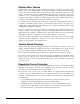
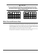
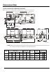
Dimensional Data
Figure 23, Dimensions, AGS 230B – AGS 320B
Note: See page 16 for lifting locations, mounting locations, weights and mounting loads.
DW
G
.
33055690
1-R2
LOCATION FAR SIDE
12.0 (304.8)
POWER ENTRY
A
AGS 230-300
26.7 (678.2)
AGS 320
25.7 (652.8)
B
OPENING FOR
CHILLER WATER PIPING
FE
POWER ENTRY
100.4
(2550.4)
SINGLE POINT POWER ENTRY "D"
5.5
(139.7)
C
36.9
(937.3)
51.1
(1297.9)
INLET
OUTLET
SINGLE POINT POWER
BOX OPTION
CONTROL
PANEL
CIRCUIT #2
CONTROL
PANEL
CIRCUIT #1
POWER ENTRY POINT
0.875 (22.2) KNOCK-OUT
POWER ENTRY POINT
0.875 (22.2)
KNOCK-OUT
FIELD CONTROL
CONNECTION
88.0
(2235.2)
X
44.0
(1117.6)
36.0
(914.4)
NOTE: Chilled water piping must enter and exit the unit platform between the base rail and the bottom of
the condenser coil in the “F” dimension on the side shown above.
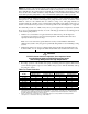
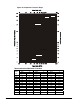
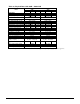
Dimensions
inches (mm)
Water Piping
inches (mm)
Fan Modules
Center of
Gravity
in. (mm)
AGS Unit
Size
A B C D E F
Connection
Sizes
inches (mm)
X
No. of
Fans
1
2
AGS 230
278.8
(7081.5)
133.4
(3388.4)
78.4
(1991.4)
192.6
(4892.0)
44.8
(1137.4)
30.0
(762.8)
8
(203.2)
139
(3531)
12 Fan 6 6
AGS 250
316.9
(8049.3)
133.4
(3388.4)
78.4
(1991.4)
192.6
(4892.6)
44.8
(1137.4)
30.0
(762.8)
8
(203.2)
146
(3708)
14 Fan 6 8
AGS 270-
320
355.2
(9022.1))
171.6
(4358.6)
116.6
(2961.6)
230.8
(5862.3
80.9
(2054.8)
31.4
(797.6)
8
(203.2)
177
(4496)
16 Fan 8 8