
Operating instructions

IMM AGSB-60 23
Operating Limits:
Maximum standby ambient temperature, 130°F (55°C)
Maximum operating ambient temperature, 115°F (46°C), or 125°F (52°C) with optional high
ambient package
Minimum operating ambient temperature (standard), 35°F (2°C)
Minimum operating ambient temperature (optional low-ambient control), 0°F (-18°C)
Leaving chilled water temperature, 40°F to 50°F (4.4°C to 10°C)
Leaving chilled fluid temperature (with anti-freeze), 20°F to 50°F (7°C to 10°C)
Operating Delta-T range, 6 degrees F to 16 degrees F (3.3 C to 8.8 C)
Maximum operating inlet fluid temperature, 66°F (19°C)
Maximum startup inlet fluid temperature, 90°F (32°C)
Maximum non-operating inlet fluid temperature, 100°F (38°C)
NOTE: Contact the local McQuay sales office for operation outside of these limits.
Flow Switch
A water flow switch must be mounted in the leaving chilled water line to prove that there is
adequate water flow to the evaporator before the unit can start. It also serves to shut down the
unit in the event that water flow is interrupted in order to guard against evaporator freeze-up.
A flow switch is available from McQuay under ordering number 017503300. It is a paddle-
type switch and adaptable to any pipe size from 1" (25mm) to 8" (203mm) nominal.
Certain minimum flow rates are required to close the switch and are listed in Table 14.
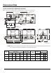
Installation should be as shown in Figure 20.
Electrical connections in the unit control center should be made at terminals 60 and 67. The
normally open contacts of the flow switch should be wired between these two terminals. Flow
switch contact quality must be suitable for 24 VAC, low current (16ma). Flow switch wire
must be in separate conduit from any high voltage conductors (115 VAC and higher) and have
an insulation rating of 600 volts.
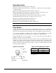
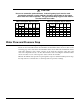
Figure 20, Flow Switch
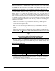
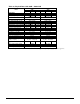
Table 14, Switch Minimum Flow Rates
NOMINAL PIPE
SIZE
INCHES (MM)
MINIMUM REQUIRED FLOW
TO ACTIVATE SWITCH
GPM (LPS)
5 (127) 58.7 (3.7)
6 (152) 79.2 (5.0)
8 (203) 140 (8.8)
Note: Water pressure differential switches are not recommended for
outdoor applications.
Flow direction marked
on switch
1" (25mm) NPT flow
switch connection
Tee
1 1/4" (32mm) pipe
dia. min. before switch
1 1/4" (32mm) pipe
dia. min. after switch