
Operating instructions

IMM AGSB-60 19
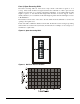
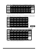
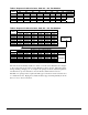
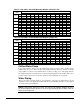
Table 11, AGS 340B - AGS 475B Mounting Weights (Aluminum Fin)
Mounting Loads for Each Point lb. (kg)
AGS
Model
M1 M2 M3 M4 M5 M6 M7 M8 M9 M10 M11 M12
lbs 1798 2442 1787 2426 2426 1787 2442 1798 1726 1557 1645 1484
340B
kg 816 1109 811 1101 1101 811 1109 816 784 707 747 674
lbs 1885 2511 1981 2638 2638 1981 2511 1885 1973 1803 1867 1706
370B
kg 856 1140 899 1198 1198 899 1140 856 896 819 847 775
lbs 1885 2511 1981 2638 3055 2357 2562 1977 1973 1803 1867 1706
400B
kg 856 1140 899 1198 1387 1070 1163 897 896 819 847 775
lbs 1977 2562 2357 3055 3055 2357 2562 1977 1973 1803 1867 1706
420B
kg 897 1163 1070 1387 1387 1070 1163 897 896 819 847 775
lbs 1999 2579 2425 3128 3128 2425 2579 1999 1973 1803 1867 1706
440B
kg 908 1171 1101 1420 1420 1101 1171 908 896 819 847 775
lbs 1999 2579 2425 3128 3128 2425 2579 1999 1973 1803 1867 1706
450B
kg 908 1171 1101 1420 1420 1101 1171 908 896 819 847 775
lbs 1999 2579 2425 3128 3128 2425 2579 1999 1973 1803 1867 1706
475B
kg 908 1171 1101 1420 1420 1101 1171 908 896 819 847 775
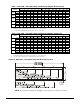
Table 12, AGS 340B - AGS 475B Mounting Weights (Copper Fin)
Mounting Loads for Each Point lb. (kg)
AGS
Model
M1 M2 M3 M4 M5 M6 M7 M8 M9 M10 M11 M12
lbs 2035 2679 2024 2663 2663 2024 2679 2035 1963 1794 1882 1721
340B
kg 924 1216 919 1209 1209 919 1216 924 891 814 854 781
lbs 2148 2774 2244 2901 2901 2244 2774 2148 2236 2066 2130 1969
370B
kg 975 1260 1019 1317 1317 1019 1260 975 1015 938 967 894
lbs 2175 2801 2271 2928 3345 2647 2852 2267 2263 2093 2157 1996
400B
kg 987 1272 1031 1329 1518 1202 1295 1029 1027 950 979 906
lbs 2293 2878 2673 3371 3371 2673 2878 2293 2289 2119 2183 2022
420B
kg 1041 1307 1214 1530 1530 1214 1307 1041 1039 962 991 918
lbs 2315 2895 2741 3444 3444 2741 2895 2315 2289 2119 2183 2022
440B
kg 1051 1314 1244 1564 1564 1244 1314 1051 1039 962 991 918
lbs 2315 2895 2741 3444 3444 2741 2895 2315 2289 2119 2183 2022
450B
kg 1051 1314 1244 1564 1564 1244 1314 1051 1039 962 991 918
lbs 2315 2895 2741 3444 3444 2741 2895 2315 2289 2119 2183 2022
475B
kg 1051 1314 1244 1564 1564 1244 1314 1051 1039 962 991 918
Chilled Water Pump
It is required that the starter(s) for the chilled water pump be wired to and controlled by the
chiller's microprocessor. The controller will energize the pump whenever at least one circuit
on the chiller is enabled to run, whether there is a call for cooling or not. The pump will also
be energized when the controller senses a near-freezing temperature at the chiller outlet sensor
to assist in freeze protection. Connection points are shown in Figure 27 on page 40.
Water Piping
Due to the variety of piping practices, it is advisable to follow the recommendations of local
authorities. They can supply the installer with the proper building and safety codes required
for a safe and proper installation.
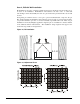
NOTE: Chilled water piping must enter and exit the unit platform between the base
rail and the bottom of the condenser coil in the approximately 30-inch width shown on
Figure 23 and Figure 24.