
Operating instructions

IMM AGSB-60 17
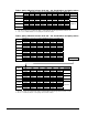
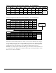
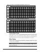
Table 7, AGS 230B - AGS 320B Lifting and Mounting Weights (Aluminum Fin)
Lifting Weight for Each Point lb. (kg) Mounting Loads for Each Point lb. (kg)
AGS
Model
L1 L2 L3 L4 L5 L6 M1 M2 M3 M4 M5 M6 M7 M8
Lbs. 2183 3043 2563 2563 3043 2183 1683 2325 1681 2322 2322 1681 2325 1683
230B
(kg) 991 1382 1164 1164 1382 991 764 1055 763 1054 1054 763 1055 764
Lbs. 2183 3043 2700 2704 3374 2509 1683 2325 1681 2322 2693 2018 2421 1814
250B
(kg) 991 1382 1226 1228 1532 1139 764 1055 763 1054 1223 916 1099 824
Lbs. 2509 3374 2841 2841 3374 2509 1814 2421 2018 2693 2693 2018 2421 1814
270B
(kg) 1139 1532 1290 1290 1532 1139 824 1099 916 1223 1223 916 1099 824
Lbs. 2520 3383 2871 2871 3383 2520 1821 2425 2043 2721 2721 2043 2425 1821
300B
(kg) 1144 1536 1304 1304 1536 1144 827 1101 928 1235 1235 928 1101 827
Lbs. 2550 3407 2956 2956 3407 2550 1838 2435 2111 2797 2797 2111 2435 1838
320B
(kg) 1158 1547 1342 1342 1547 1158 834 1106 958 1270 1270 958 1106 834
NOTES:
1. Lifting tabs with 2 ½ in. (63.5 mm) holes at location "L" on side of base rail.
2. 1 in. (25.4 mm) mounting holes at location "M" on bottom of base rails.
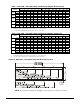
Table 8, AGS 230B - AGS 320B Lifting and Mounting Weights (Copper Fin)
Lifting Weight for Each Point lb. (kg) Mounting Loads for Each Point lb. (kg)
AGS
Model
L1 L2 L3 L4 L5 L6 M1 M2 M3 M4 M5 M6 M7 M8
Lbs. 2499 3359 2879 2879 3359 2499 1920 2562 1918 2559 2559 1918 2562 1920
230B
(kg) 1135 1525 1307 1307 1525 1135 872 1163 871 1162 1162 871 1163 872
Lbs. 2552 3412 3069 3073 3743 2878 1960 2602 1958 2599 2970 2295 2698 2091
250B
(kg) 1158 1549 1393 1395 1699 1306 890 1181 889 1180 1348 1042 1225 949
Lbs. 2930 3795 3262 3262 3795 2930 2130 2737 2334 3009 3009 2334 2737 2130
270B
(kg) 1330 1723 1481 1481 1723 1330 967 1243 1060 1366 1366 1060 1243 967
Lbs. 2941 3804 3292 3292 3804 2941 2137 2741 2359 3037 3037 2359 2741 2137
300B
(kg) 1335 1727 1495 1495 1727 1335 970 1244 1071 1379 1379 1071 1244 970
Lbs. 2971 3828 3377 3377 3828 2971 2154 2751 2427 3113 3113 2427 2751 2154
320B
(kg) 1349 1738 1533 1533 1738 1349 978 1249 1102 1413 1413 1102 1249 978
NOTES:
1. Lifting tabs with 2½ in. (63.5 mm) holes at location "L" on side of base rail.
2. 1 in. (25.4 mm) mounting holes at location "M" on bottom of base rails.
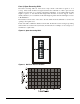
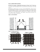
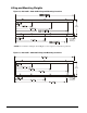
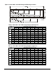
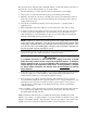
Figure 18, AGS 340B – AGS 400B Lifting and Mounting Locations
2 (51)
Typical Spacing
for Isolator
Mounting (8)
88.0
(2235.2)
NOTE: For orientation, in Figure 18 and Figure 19, the evaporator connections point left.