Installation and Maintenance Manual IMM AGSB-60 Group: Chiller Part Number: 330412001 Date: October 2005 Supersedes: IMM AGS-1 GeneSys™ Air-Cooled Screw Compressor Chiller AGS 230B through AGS 475B 60 Hertz R-134a
Table Of Contents Introduction........................................3 Component Location....................... 48 General Description ...................................3 Nomenclature.............................................3 Inspection...................................................3 Major Component Location .....................48 Power Panel .............................................50 Control Panel ...........................................51 Installation and Start-up..................
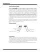
Introduction General Description McQuay GeneSys™ air-cooled water chillers are complete, self-contained, automatic refrigerating units that include the latest in engineered components, arranged to provide a compact and efficient unit. Each unit is completely assembled, factory wired, evacuated, charged, tested and comes complete and ready for installation.
Installation and Start-up Note: Installation and maintenance are to be performed only by qualified personnel who are familiar with local codes and regulations, and experienced with this type of equipment. WARNING Sharp edges and coil surfaces are a potential injury hazard. Avoid contact with them. Start-up by McQuayService is included on all units sold for installation within the USA and Canada and must be performed by them to initiate the standard limited product warranty.
Location Locate the unit to provide proper airflow to the condenser. (See Figure 2 on page 6 for required clearances). Due to the shape of the condenser coils on the AGS chillers, orient the unit so that prevailing winds blow parallel to the unit length, thus minimizing the wind effect on condensing pressure and performance. If low ambient temperature operation is expected, it is recommended that optional wind baffles or louvers be field installed if the unit has no protection against prevailing winds.
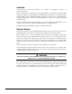
Clearance Requirements Figure 2, Clearance Requirements, AGS 230B – 475B 5’-0” if open fence or 50% open wall 6’-0” if solid wall (see note 3 for pit) 5’-0” if open fence or 50% open wall 6’-0” if solid wall (see note 3 for pit) See notes 2 & 4 concerning wall height at unit sides. No obstructions. Recommended area required for unit operation, air flow and maintenance access. 10’-0” min.
Restricted Airflow General The clearances required for design operation of AGS air-cooled condensers are described in the previous section. Occasionally, these clearances cannot be maintained due to site restrictions such as units being too close together or a fence or wall restricting airflow, or both. The McQuay AGS chillers have several features that can mitigate the problems attributable to restricted airflow.
Case 1, Building or Wall on One Side of One Unit The existence of a screening wall, or the wall of a building, in close proximity to an air-cooled chiller is common in both rooftop and ground level applications. Hot air recirculation on the coils adjoining the wall will increase compressor discharge pressure, decreasing capacity and increasing power consumption. When close to a wall, it is desirable to place chillers on the north or east side of them.
Case 2, Two Units Side By Side Two or more units sited side by side are common. If spaced closer than 12 feet (3.7 meters) it is necessary to adjust the performance of each unit; circuits adjoining each other are affected. If one of the two units also has a wall adjoining it, see Case 1. Add the two adjustment factors together and apply to the unit located between the wall and the other unit. Mounting units end to end will not necessitate adjusting performance.
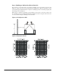
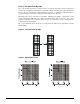
Case 3, Three or More Units Side By Side When three or more units are side by side, the outside units (chillers 1 and 3 in this case) are influenced by the middle unit only on their inside circuits. Their adjustment factors will be the same as Case 2. All inside units (only chiller 2 in this case) are influenced on both sides and must be adjusted by the factors shown below. Figure 8, Three or More Units Chiller 1 Chiller 2 Chiller 3 Figure 9, Adjustment Factor 4.0 8.0 3.0 6.0 2.0 4.0 1.0 2.
Case 3, Open Screening Walls Decorative screening walls are often used to help conceal a unit either on grade or on a rooftop. These walls should be designed such that the combination of their open area and distance from the unit do not require performance adjustment. It is assumed that the wall height is equal to, or less than the unit height when mounted on its base support. This is usually satisfactory for concealment. If the wall height is greater than the unit height, see Case 4, Pit Installation.
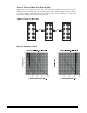
Case 4, Pit/Solid Wall Installation Pit installations can cause operating problems and great care should be exercised if they are to be used on an installation. Recirculation and restriction can both occur. A solid wall surrounding a unit is substantially the same as a pit and the data presented in this case should be used. Steel grating is sometimes used to cover a pit to prevent accidental falls or trips into the pit.
Vibration Isolators Vibration isolators are recommended for all roof-mounted installations or wherever vibration transmission is a consideration. The following section "Lifting and Mounting Weights" contains the location of unit lifting holes and the load at each location. Mounting holes dimensions and the bearing weight at each hole given. Table 1, Spring Flex Isolator Data Housing Spring Color CP-2-27 Orange CP-2-28 Green CP-2-31 Gray CP-2-32 White Max. Load Each Lbs. (kg) Defl. In.
Table 3, Spring Vibration Isolators, AGS 230 – 320, Part Numbers and Spring Colors Model AGS230 AGS250 AGS270 AGS300 AGS320 M1 CP-2-28 Green CP-2-28 Green CP-2-28 Green CP-2-28 Green CP-2-28 Green Mounting Location (See Footprint Drawings Figure 16 or M2 M3 M4 M5 M6 M7 CP-2-31 CP-2-28 CP-2-31 CP-2-31 CP-2-28 CP-2-31 Gray Green Gray Gray Green Gray CP-2-31 CP-2-28 CP-2-31 CP-2-32 CP-2-31 CP-4-26 Gray Green Gray White Gray Purple CP-4-26 CP-2-31 CP-2-32 CP-2-32 CP-2-31 CP-4-26 Purple Gray White White Gray P
Table 5, Neoprene-in-Shear Isolators, AGS 230 – 320, Part Numbers Model M1 Mounting Location (See Footprint Drawings Figure 16 or Figure 17) M2 M3 M4 M5 M6 M7 M8 Kit Number AGS230 4-RED 4-RED 4-RED 4-RED 4-RED 4-RED 4-RED 4-RED 350348201 AGS250 4-RED 4-RED 4-RED 4-RED 4-GREEN 4-RED 4-RED 4-RED 350348202 AGS270 4-RED 4-RED 4-RED 4-GREEN 4-GREEN 4-RED 4-RED 4-RED 350348203 AGS300 4-RED 4-RED 4-RED 4-GREEN 4-GREEN 4-RED 4-RED 4-RED AGS320 4-RED 4-RED 4-RED 4-GREEN 4-GREEN 4-RED 4-RED 4-RED Note: The same i
Lifting and Mounting Weights Figure 16, AGS 230B – AGS 250B Lifting and Mounting Locations 88.0 (2235.2) 2 (51) Typical Spacing for Isolator Mounting (8) NOTE: For orientation, in Figure 16 and Figure 17, the evaporator connections point left. Figure 17, AGS 270B - AGS 320B Lifting and Mounting Locations 88.0 (2235.
Table 7, AGS 230B - AGS 320B Lifting and Mounting Weights (Aluminum Fin) AGS Model 230B 250B 270B 300B 320B Lbs. Lifting Weight for Each Point lb. (kg) Mounting Loads for Each Point lb. (kg) L1 L2 L3 L4 L5 L6 M1 M2 M3 M4 M5 M6 M7 M8 2183 3043 2563 2563 3043 2183 1683 2325 1681 2322 2322 1681 2325 1683 (kg) 991 1382 1164 1164 1382 991 764 1055 763 1054 1054 763 1055 764 Lbs.
Figure 19, AGS 420B - AGS 475B Lifting and Mounting Locations 88.0 (2235.2) 2 (51) Typical Spacing for Isolator Mounting (8) Table 9, AGS 340B - AGS 475B Lifting Weights (Aluminum Fin) Lifting Weight for Each Point AGS Model 340B 370B 400B 420B 440B 450B 475B lb.
Table 11, AGS 340B - AGS 475B Mounting Weights (Aluminum Fin) Mounting Loads for Each Point AGS Model 340B 370B 400B 420B 440B 450B 475B lb.
The piping should be designed with a minimum number of bends and changes in elevation to keep system cost down and performance up. It should contain: 1. Vibration eliminators to reduce vibration and noise transmission to the building. 2. Shutoff valves to isolate the unit from the piping system during unit servicing. 3. Manual or automatic air vent valves at the high points of the system and drains at the low parts in the system.
System Water Volume It is important to have adequate water volume in the system to provide an opportunity for the chiller to sense a load change, adjust to the change and stabilize. As the expected load change becomes more rapid, a greater water volume is needed. The system water volume is the total amount of water in the evaporator, air handling products and associated piping.
NOTE: The heaters come from the factory connected to the control power circuit. If desired, the 3 KVA control transformer can be unwired and a field 115-volt power source wired to terminals TB1-1 and TB1-2 in the control panel for circuit #1 (do not wire directly to the heater). If this is done, the disconnect switch should be clearly marked to avoid accidental deactivation of the heater during freezing temperatures. Exposed chilled water piping also requires protection.
Operating Limits: Maximum standby ambient temperature, 130°F (55°C) Maximum operating ambient temperature, 115°F (46°C), or 125°F (52°C) with optional high ambient package Minimum operating ambient temperature (standard), 35°F (2°C) Minimum operating ambient temperature (optional low-ambient control), 0°F (-18°C) Leaving chilled water temperature, 40°F to 50°F (4.
Figure 21, Typical Field Water Piping Vent In Flow Switch Out Gate Valve Drain Valved Pressure Gauge Vibration Eliminator Water Strainer Vibration Eliminator Balancing Valve Protect All Field Piping Against Freezing Gate Valve Notes: 1. Connections for vent and drain fittings are located on the top and bottom of both evaporator water heads. 2. Piping must be supported to avoid putting strain on the evaporator nozzles.
CAUTION Do not use automotive grade antifreeze. Industrial grade glycols must be used. Automotive antifreeze contains inhibitors that will cause plating on the copper tubes within the chiller evaporator. The type and handling of glycol used must be consistent with local codes. Table 15, Ethylene Glycol Factors % E.G Freeze Point o o F C PD Table 16, Propylene Glycol Factors % P.G Freeze Point o o F C Cap. Power Flow -3.3 0.994 0.998 1.036 1.104 10 26 Cap. Power Flow PD -3.3 0.985 0.993 1.
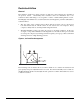
Figure 22, Evaporator Pressure Drops AGS 340 AGS 300 AGS 230-270 AGS 440-475 AGS 370-420 AGS 320 Minimum/Nominal/Maximum Flow Rates AGS Unit Size 230B 250B 270B 300B 320B 340B 370B 400B 420B 440B 450B 475B 26 Minimum Flow Flow ΔP gpm ft. 330 365 401 424 451 501 540 576 613 640 660 680 5.3 6.5 7.8 6.1 4.9 7.0 6.1 6.8 7.5 6.4 6.7 7.1 Nominal Flow Flow ΔP gpm ft.
Physical Data Table 17, Physical Data, AGS 230B – AGS 270B DATA 230B Ckt 1 250B Ckt 2 Ckt 1 270B Ckt 2 BASIC DATA Cap. @ ARI Conditions, tons (kW) 220.5 (774) 243.9 (856) Unit Operating Charge lbs (kg) 298 (135) 298 (135) 298 (135) 321 (145) Cabinet Dimensions 278 x 88 x 100 317 x 88 x 100 L x W x H, in. (mm) (7087 x 2235 x 2550) (8052 x 2235 x 2550) Unit Operating Weight, lbs.
NOTE: Weights shown are for aluminum fin coils. Add 158 lbs. (72 kg) per fan to operating or shipping weights for copper fins. Table 19, Physical Data, AGS 340B – AGS 400B DATA Ckt. 1 340B Ckt. 2 Ckt. 3 AGS MODEL NUMBER 370B Ckt. 1 Ckt. 2 Ckt. 3 BASIC DATA Unit Cap. @ ARI, tons (kW) Unit Operating Charge, lbs (kg) 334.1 (1173) 360.0 (1264) 285 (129) 285 (129) 285 (129) 312 (141) 312 (141) 312 (141) 434 x 88 x 100 472 x 88 x 100 Cabinet Dim., L x W x H, in.
Table 21, Physical Data, AGS 450B – AGS 475B AGS MODEL NUMBER DATA Ckt. 1 450B Ckt. 2 Ckt. 3 Ckt. 1 475B Ckt. 2 Ckt. 3 BASIC DATA Unit Cap. @ ARI, tons (kW) Unit Operating Charge, lbs (kg) 440.5 (1546) 453.9 (1593) 358 (162) 358 (162) 358 (162) 358 (162) 358 (162) 358 (162) 548 x 88 x 100 548 x 88 x 100 Cabinet Dim., L x W x H, in. (mm) (13919 x 2235 x 2550) (13919 x 2235 x 2550) Unit Operating Weight, lbs.
Dimensional Data Figure 23, Dimensions, AGS 230B – AGS 320B Note: See page 16 for lifting locations, mounting locations, weights and mounting loads. 5.5 (139.7) SINGLE POINT POWER ENTRY "D" INLET SINGLE POINT POWER BOX OPTION POWER ENTRY POINT 0.875 (22.2) KNOCK-OUT FIELD CONTROL CONNECTION CONTROL PANEL CIRCUIT #1 51.1 (1297.9) 36.9 (937.3) CONTROL PANEL CIRCUIT #2 OUTLET E POWER ENTRY POINT 0.875 (22.2) KNOCK-OUT F OPENING FOR CHILLER WATER PIPING C 100.4 (2550.4) 36.0 (914.
Figure 24, Dimensions, AGS 340B –475B Note: See page 16 for lifting locations, mounting locations, weights and mounting loads. SINGLE POINT POWER ENTRY "D" INLET FIELD CONTROL CONNECTION POWER ENTRY POINT 5.5 (139.7) SINGLE POINT POWER BOX OPTION 0.875 (22.2) KNOCK-OUT CONTROL PANEL CIRCUIT #1 H J CONTROL PANEL CONTROL PANEL CIRCUIT #3 CIRCUIT #2 OUTLET POWER ENTRY POINT 0.875 (22.2) KNOCK-OUT POWER ENTRY POINT 0.875 (22.2) KNOCK-OUT G F OPENING FOR CHILLER WATER PIPING C 100.41 (2550.
Wind Baffles and Hail Guards Wind Baffles/Hail Guards are a field installed option that are used to stabilize unit operation in high wind areas and to assist in operation at low ambient temperatures. Figure 25 shows a typical panel assembly on an AGS unit. The actual number of panels and parts will vary by model size. The parts are shown in the table below and referenced by balloon numbers. The baffles extend out 20 inches from each side.
Table 22, Packing List Description Vertical Support Rib Top Cover Front Panel ¼ - 20 x ½” Screw (Place in Poly Bag) Part Number 074758501 330409401 330409501 046093807 Bubble Number 1 2 3 Figure 26, Components TOP REAR (AGAINST UNIT) VERTICAL SUPPORT RIB TOP COVER FRONT PANEL Top Panel, Install Last Overlap the Front panel Front Panel, Install Second Rib, Install First IMM AGSB-60 33
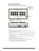
Electrical Data Field Wiring General Wiring must comply with all applicable codes and ordinances. Damage to the equipment caused by wiring not complying with specifications is not covered under warranty. An open fuse or circuit breaker indicates a short, ground, or overload. Before replacing a fuse or restarting a compressor or fan motor, the trouble must be found and corrected. Copper wire is required for all power lead terminations at the unit and copper must be used for all other wiring to the unit.
Table 23, AGS 230B – AGS 475B, Electrical Data, Optional Single-Point POWER SUPPLY FIELD FUSE SIZE or HACR BREAKER SIZE MINIMUM CIRCUIT AMPACITY (MCA) QTY 60 475 418 6 6 WIRE GAUGE 250 4/0 460 575 60 519 447 6 6 300 4/0 2 2 3.0 2.0 600 500 700 600 270 460 575 60 555 471 6 6 300 250 2 2 3.0 2.5 700 600 700 600 300 460 575 60 586 496 6 6 350 250 2 2 3.0 2.5 700 600 800 700 320 460 575 60 611 516 6 6 350 300 2 2 3.0 3.
Table 25, AGS 340B–AGS 475B, Electrical Data, Standard Multiple-Point, (Circuits # 1 & 2) ELECTRICAL CIRCUIT 1 (COMP 1) AGS UNIT SIZE 340 370 400 420 440 450 475 POWER SUPPLY MIN. HUB VOLTS HZ CIRCUIT FIELD WIRE (Conduit AMPS Connection) (MCA) WIRE HUB QTY QTY GAUGE SIZE 460 575 460 575 460 575 460 575 460 575 460 575 460 575 60 60 60 60 60 60 60 ELECTRICAL CIRCUIT 2 (COMP 2) FIELD FUSING POWER SUPPLY MIN.
Table 26, AGS230B–AGS 475B, Compressor and Condenser Fan Motor Amp Draw AGS UNIT SIZE 230 250 270 300 320 340 370 400 420 440 450 475 RATED LOAD AMPS VOLTS 460 575 460 575 460 575 460 575 460 575 460 575 460 575 460 575 460 575 460 575 460 575 460 575 HZ CIRCUIT #1 CIRCUIT #2 195 171 195 171 225 190 225 190 250 210 195 171 195 171 195 171 225 190 225 190 225 190 250 210 195 171 225 190 225 190 250 210 250 210 195 171 195 171 225 190 225 190 225 190 250 210 250 210 60 60 60 60 60 60 60 60 60 60 60 60
Table 28, AGS 230B–AGS 475B, Wiring Information with Multiple-Point AGS UNIT SIZE 230 250 270 300 320 340 370 400 420 440 450 475 VOLTS HZ 460 575 460 575 460 575 460 575 460 575 460 575 460 575 460 575 460 575 460 575 460 575 460 575 TERMINAL SIZE (AMPS) CKT 1 CKT 2 CKT 3 WIRING TO UNIT POWER BLOCK CONNECTOR WIRE RANGE PER PHASE (COPPER WIRE ONLY) CKT 1 CKT 2 CKT 3 60 400 400 -- #6-350 #6-350 -- 60 400 400 -- #6-350 #6-350 -- 60 400 400 -- #6-350 #6-350 -- 60 400 400 -- #6-350
Electrical Data Notes 1. Allowable voltage limits Unit nameplate 460V/60Hz/3Ph: 414V to 506V Unit nameplate 575V/60Hz/3Ph: 518V to 632V 2. Unit wire size ampacity (MCA) is equal to 125% of the largest compressor-motor RLA plus 100% of RLA of all other loads in the circuit. 3. Single point power supply requires a single disconnect to supply electrical power to the unit. This power must be fused. 4. All field wiring to unit power block or optional nonfused disconnect switch must be copper. 5.
Field Wiring Diagram Figure 27, Typical Field Wiring Diagram, Circuit #1 Control Box Note: Field-wired control connections are made in the control panel for circuit 1 only. UNIT MAIN TERMINAL BLOCK DISCONNECT (BY OTHERS) GND LUG 3 PHASE TO COMPRESSOR(S) AND FAN MOTORS POWER SUPPLY FUSED CONTROL CIRCUIT TRANSFORMER 120 VAC NOTE: ALL FIELD WIRING TO BE TB1 (115 VAC) INSTALLED AS NEC CLASS 1 TB1-2 WIRING SYSTEM WITH CONDUCTOR 1 RATED 600 VOLTS 120 VAC 82 CHW PUMP RELAY #1 (BY OTHERS) 120 VAC 1.
Solid State Starters Solid state starters are standard on all AGS units. A solid state starter uses a silicon-controlled rectifier (SCR) power section to allow a motor to be brought to full speed with a reduced initial voltage that increases to full line voltage over a given time. The McQuay motor starter, custom designed for this specific application, is microprocessor controlled. Along with this starting technique, the motor starter also provides protection for the motor and monitors its load conditions.
OL OL will alternately blink with the normal display on the LED display when motor thermal overload content has reached 90% to 99% of its capacity. OLL The motor thermal overload content has reached 100%, and the motor has stopped. The motor cannot be restarted until the overloaded motor has cooled and OLt is displayed. OLt The motor thermal overload content has been reduced to 60% or less, and the motor can be restarted. ena Passcode protection is enabled. dis Passcode is disabled.
CODE F1 F3 F5 F6 F23 F24 F29 F30 F31 F52 F54 F55 F70 F71 F73 F74 F75 CRITICAL YES YES F77 F78 F90 YES YES YES F91 F92 F97 F98 F99 YES YES YES YES YES YES YES YES DESCRIPTION Line phase sequence not ABC System power is not three phase Line frequency less than 25hz. Line frequency greater than 72hz. Line current unbalance greater than set level. Line currents are very unbalanced.
Figure 28, Trouble Shooting Guide Start 3 Yes Low or Missing Line? No 4 1 No Fuses OK? Yes Replace Fuses No Yes Phase Order Fault No 2 Circuit Breaker OK? 5 Swap Any 2 Power Leads Yes Thermal Trip? Yes No 6 Replace Circuit Breaker Yes No In-Line OK? Interlock Open? No Yes 7 Correct Inline Fault Correct Power Source Problem 8 No No High Ambient? Wiring OK? Yes Yes 9 Replace Control Card Correct and Wait to Cool Yes Bad Air Circulation? No Correct Interlock State No Return T
From Previous Page 11 Current Imbalance Fault? No Yes 7 No Fuses Blown or Breaker Tripped? Wiring Good? Yes Yes 12 Motor Winding Short? Correct Wiring No Yes Replace Fuse or Reset Breaker No 13 No 12 No SCRs OK? Motor Problem? Yes Replace Defective SCRs 14 All Gate Pulses Present? Yes 15 Yes CT Burden Switches Set Correctly? Repair or Replace Motor No Replace Control Card Return to Normal Operation No Yes Contact Benshaw For Assistance Replace Control Card No Check Jumpers P
FLOW CHART DETAILS: 1. Fuses Determine if power line fuses have been installed, and if they are operating properly. 2. Circuit Breaker Determine if the circuit breaker is off, or has tripped and disconnected the line from the starter. 3. Power Line Voltage Verify that line voltage is present, and is the correct voltage. 4. Phase Order Fault If Fault Codes F1 or F2 are displayed on the control card LED display, exchange any two incoming power line cable connections. 5.
Solid State Starter Settings Operating Parameters Settings for Default Value and Settable Range: IMM AGSB-60 No. P1 P2 P3 P4 P5 P6 P7 P8 P9 P10 P11 P12 P13 P14 P15 P16 P17 Operating Parameter Motor Full Load Amps (FLA) Motor Rated Load Amps (RLA) Initial Motor Starting Current Max.
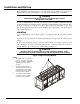
Component Location Major Component Location Figure 29, Two-Compressor Unit Cutaway Control/Power Panel Circuit #1 Condenser Section Circuit #2 Two-Circuit Flooded Evaporator Compressor #1 Compressor #2 Control/Power Panel Circuit #2 Oil Separator #1 48 IMM AGSB-60
Figure 30, Piping Schematic AIR FLOW S02 S05 CHECK VALVE CHARGING VALVE SCHRADER VALVE RELIEF VALVE DISCHARGE TUBING SCHRADER (EACH DISCH HEADER) OIL SEPARATOR DISCHARGE TUBING ANGLE VALVE OIL FILTER SIGHT GLASS SIGHT GLASS CONDENSER ASSEMBLY CONDENSER ASSEMBLY AIR FLOW S01 S04 S07 RELIEF VALVE (EVAP SHELL) TO REAR OF COMPRESSOR SUCTION AIR FLOW AIR FLOW BUTTERFLY VALVE (OPTION) CHARGING VALVE SOLENOID VALVE LIQUID SHUT-OFF VALVE WATER OUT FILTER DRIER OIL RETURN SCHRADER S09 S08
Power Panel Each compressor and its associated refrigerant circuit and controlled devices have a dedicated power and control system. They are contained in a duplex panel, the outer box containing the MicroTech II microprocessor with related accessories and the inner box containing the power components including the starter.
Control Panel The control panel for Circuit #1 is shown below. The panel for circuit #2 and #3 is similar but does not contain the Unit Controller. Distributed control architecture enhances unit reliability. Each compressor circuit has its own microprocessor controller so that if one controller is inoperative, the other compressor(s) will be allowed to run. EWHR, Evaporator Heater Relay T4, Load/ Unload Solenoid Transformer T3, Control Transformer MHPR, Mech.
Optional Features There are a number of options that may or may not be present on any specific unit. These options can affect unit control operation and how a unit is installed and wired. Controls Low Ambient Head Pressure Control Optional VFD head pressure control on first two fans permits unit operation down to 0°F (-18°C) ambient (balance of fans are staged on and off). However, since the actual minimum ambient can be dependent on wind conditions, wind baffles are also available.
Multi-Point w/Disconnect Switch Separate power supply to each circuit's power panel which is equipped with a disconnect switch with a through-the-door handle. Each disconnect switch can isolate its circuit for service purposes. Single-Point w/ Disconnect Switch Single power supply to a factory-mounted disconnect switch. Includes factory wiring to a circuit breaker located in each circuit's power panel.
Start-up and Shutdown NOTICE McQuayService personnel or factory authorized service agency must perform initial start-up in order to activate warranty. CAUTION Most relays and terminals in the unit control center are powered when S1 is closed and the control circuit disconnect is on. Therefore, do not close S1 until ready for start-up or the unit may start unintentionally. Switches There is a single unit on-off switch, S1, located in the control box for circuit #1.
CAUTION The unit has a one-time pumpdown operation. When the CS switches are in the off position the unit will pumpdown once and not run again until the switches are moved to the on position. If the CS switches are in the on position and the load has been satisfied, the unit will go into one-time pumpdown and will remain off until the MicroTech II control senses a call for cooling and starts the circuit. Under no circumstance use the compressors for pumpdown of the system with the liquid line valves closed.
Start-up After Extended (Seasonal) Shutdown 1. With all electrical disconnects locked and tagged open, check all screw or lug-type electrical connections to be sure they are tight for good electrical contact. 2. Check the voltage of the unit power supply and see that it is within the ±10% tolerance that is allowed. Voltage unbalance between phases must be within ±2%. 3. See that all auxiliary control equipment is operative and that an adequate cooling load is available for start-up. 4.
System Maintenance General On initial start-up and periodically during operation, it will be necessary to perform certain routine service checks. Among these are checking the liquid line sight glasses, evaporator sight glasses, and oil separator sight glasses, plus taking a full set of refrigerant pressure and temperature readings. Through the MicroTech II keypad, check to see that the unit has normal superheat and subcooling readings.
Electrical Terminals DANGER Electric shock hazard and risk of personal injury or death exists. Turn off all power before continuing with following service. Periodically check electrical terminals for tightness and tighten as required. Condensers The condensers are air-cooled and constructed of 3/8" (9.5mm) OD internally finned copper tubes bonded in a staggered pattern into louvered aluminum (standard material) fins.
NOTE: Exceeding normal charge can result in abnormally high discharge pressure and relief valve discharge, or cause low discharge superheat resulting in oil loss into the system. An element inside the sight glass indicates the moisture condition corresponding to a given element color. The color code is printed on the edge of the sight glass. If the sight glass does not indicate a dry condition after about 12 hours of operation, the circuit should be pumped down and the filter-drier changed.
Preventative Maintenance Schedule PREVENTATIVE MAINTENANCE SCHEDULE OPERATION General Complete unit log and review (Note 3) Visually inspect unit for loose or damaged components and visible leaks Inspect thermal insulation for integrity Clean and paint as required WEEKLY Condenser (air-cooled) Clean condenser coils (Note 4) Check fan blades for tightness on shaft (Note 5) Check fans for loose rivets and cracks, check motor brackets Check coil fins for damage and straighten as necessary ANNUAL (Note 2)
Service CAUTION 1. Service on this equipment is to be performed by qualified refrigeration personnel familiar with equipment operation, maintenance, correct servicing procedures, and the safety hazards inherent in this work. Causes for repeated tripping of equipment protection controls must be investigated and corrected. 2. Anyone servicing this equipment must comply with the requirements set forth by the EPA regarding refrigerant reclamation and venting.
1. On the circuit controller, under the "SET EXV SPs (2)", change the "Service Pumpdown" set point from "No" to "Yes". 2. If the circuit status is "Off:PumpDwnSw", move the circuit pumpdown switch from "Pumpdown and Stop" to "Auto". Also clear the anticycle timers through the MicroTech keypad. 3. Move the circuit switch to the OFF position. The compressor will unload to minimum slide position and the unit will pump down. 4.
extended surface and turbulent flow of water through the tubes. Normally no service work is required on the evaporator other than cleaning the water (tube) side in the event of improper water treatment or contamination. Charging Refrigerant Why does the AGS flooded evaporator use subcooling control? Subcool control maintains proper evaporator level for efficiency and is the most stable value with which to control a flooded evaporator chiller.
oil return line by incrementally closing down the ball valve. This can help maintain oil in the oil separator and higher DSH, if it is overfeeding and dropping the DSH too much. The minimum superheat the control will allow is 35 degrees F (19 degrees C) to help ensure that the DSH does not cause issues with limiting the compressor with low discharge superheat or cause oil loss. Most of the oil recovery is done through carry-over through the suction line.
Summary: At 100% slide position, in Subcool control, the DSH should be as high as possible with suction pressure at a operable value based on water/glycol mixture. At 100% load, in Subcool control, the DSH and suction pressure need to be balanced. Example: Running circuit 1 at 100% slide target, with water only in the loop, set the low evaporator pressure unload to 28psi (32°sat.) and the low evaporator pressure hold to 30psi. Run the suction pressure at approximately 32psi at full load.
Charging Oil The oil separator is equipped with two sight glasses that are used to indicate oil quantity. Oil charge determination must be done at, or near, full load. It may be normal to see the oil below the bottom sight glass while running at part load conditions due to oil laying in the compressor casting at low refrigerant flows. However, oil trips at part load indicate low oil level.
Evaporator entering water temperature - This sensor is located on the evaporator water inlet connection and is used for monitoring purposes and return water temperature reset control. Evaporator pressure transducer circuit #1, 2 (and 3) - This sensor is located on the suction side of the compressor and is used to determine saturated suction refrigerant pressure and temperature. It also provides low pressure freeze protection.
the high pressure switch will close again at 200 psig (1379 kPa), the control circuit will remain locked out and it must be reset through the MicroTech II control. The control is mounted in the control panel. Compressor motor protection The compressors are supplied with two types of motor protection. Solid state electronic overloads mounted in the control box sense motor current to within 2% of the operating amps. The MUST TRIP amps are equal to 140% of unit nameplate compressor RLA.
circuits. Although fans 5/6 and 7/8 are controlled by one contactor each, more stages are created by using virtual stages. See the table below: Table 32, Staging with VFD Stage 1 2 3 4 5 6 Fans On 1,2,3 1,2,3,4 1,2,4,5,6 1,2,3,4,5,6 1,2,3,5,6,7,8 1,2,3,4,5,6,7,8 Staging Up There are four stage-up deadbands that apply to the fan control stages. Stages one through three use their respective deadbands. Stage four to eight share the fourth stage-up deadband.
The head pressure control will provide proper operating refrigerant discharge pressures at the ambient temperatures listed for it, provided the coil is not affected by the existence of wind. Wind baffles must be utilized for low ambient operation if the unit is subjected to winds greater than 5 mph. Low ambient start Low ambient start is incorporated into the MicroTech II controller logic.
Controls, Settings and Functions Table 34, Controls DESCRIPTION FUNCTION SYMBOL SETTING RESET LOCATION Compressor Heaters To provide heat to drive off liquid refrigerant when compressor is off. HTR1-COMPR On, when compressor is off. N/A On the Compressor Compressor Solenoid - Load Loads compressor LOAD N/A N/A On the Compressor Compressor Solenoid - Unload Unloads the compressor UNLOAD N/A N/A On the Compressor Evaporator Heaters Help prevent evaporator freeze-up HTR-EVAP 38oF (3.
Troubleshooting Chart Table 35, Troubleshooting PROBLEM Compressor will not run. POSSIBLE CAUSES POSSIBLE CORRECTIVE STEPS 1. 2. 3. 4. 5. 6. Main power switch open. Unit S1 system switch open. Circuit switch, CS in pumpdown position. Chilled water flow switch not closed. Circuit breakers open. Fuse blown or circuit breakers tripped. 1. 2. 3. 4. 5. 6. 7. 8. Unit phase voltage monitor not satisfied. Compressor overload tripped. 7. 8. Close switch. Check unit status on MicroTech II display.
Periodic Maintenance Log Date of inspection: Address: Facility/job name: City/State: Unit model number: Physical location of unit: Unit serial number: Service technical (name): Software identification: Operating hours: Compressor #1 Compressor #2 Compressor #3 Number of starts Compressor #1 Compressor #2 Compressor #3 Follow up service required: Yes No General Actions to be Taken Upper part of report completed: Yes No Fill in above Compressor operation: Yes 1.
IMM AGSB-60
This document contains the most current product information as of this printing. For the most up-todate product information, please go to www.mcquay.com. © 2004 McQuay International • www.mcquay.