
Operating instructions
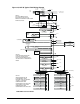
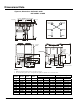
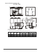
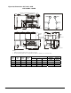

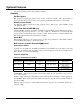


Figure 28, Dimensions: ACZ 120B - 155B
AGZ 100BM – 130BM
82.4 (2093)
34.22
(869.2)
39.95
(1014.7)
48.00
(1319.2)
53.73
(1364.7)
67.8 (1721)
12.4
(315)
25.2
(640)
2.0
(51)
2.0
(51)
COMPRESSORS CIRC #2
COMPRESSORS CIRC #1
ISOLATOR LOCATIONS ON BOTTOM OF RAIL
Z
Y
173.1 (4396)
23.9
(114)
9.0
(229)
17.6
(447)
X
100.4
(2550)
88.0 (2235)
43.8
(1111)
6.4(1624)
14.4 (365)
FIELD CONTROL
CONNECTION
POWER
ENTRY
POINT
0.875
KNOCK OUTS
DWG. #3305026
23.9
(114)
67.8 (1721)
CONTROL
PANEL
CONTROL
PANEL
SUCTION
LINE #2
SUCTION
LINE #1
HOT GAS
BYPASS #2
HOT GAS
BYPASS #1
LIQUID
LINE #2
LIQUID
LINE #1
REFRIGERANT CONNECTIONS
NOTES:
1. Hail and wind guards add 20 inches to the width of each side.
2. Be sure that the expansion valves’ sensing bulb and capillary are attached to the correct suction line.
Center of Gravity Inches (mm) Weights Lbs. (kg)
ACZ-B
AGZ-BM
Liquid
Conn.
Suction
Conn.
Unit
Size
Unit
Size
X Y Z
Shipping
Weight
Operating
Weight
120B 100BM
(2) 1 3/8 (2) 3 1/8 43 (1092) 46 (1168) 75 (1905) 6820 (3094) 6970 (3162)
130B 110BM
(2) 1 3/8 (2) 3 1/8 44 (1118) 46 (1168) 73 (1854) 7080 (3211) 7230 (3280)
140B 120BM
(2) 1 3/8 (2) 3 1/8 43 (1092) 63 (1600) 73 (1854) 7360 (3338) 7480 (3393)
155B 130BM
(2) 1 3/8 (2) 3 1/8 44 (1118) 40 (1016) 71 (1803) 7640 (3466) 7760 (3520)
54 ACZ / AGZ-BM IMM ACZ/AGZ-4