
Operating instructions


Location
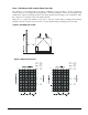
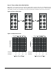
Figure 3, Clearances
Unit Placement
4 FT. (1220)
CLEARANCE FOR
SERVICE ACCESS
4 FT. (1220mm)
CLEARANCE FOR
SERVICE ACCESS
SEE TABLE BELOW
DIMENSION “A”
SEE TABLE BELOW
DIMENSION “A”
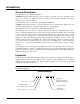
ACZ/AGZ units are for outdoor applications and can
be mounted either on a roof or at ground level. For
roof mounted applications, install the unit on a steel
channel or I-beam frame to support the unit above the
roof. For ground level applications, install the unit on
a substantial base that will not settle. A one-piece
concrete slab with footings extended below the frost
line is recommended. Be sure the foundation is level
within 1/2"(13mm) over its length and width. The
foundation must be strong enough to support the
weights listed in the Physical Data Tables beginning
on page
28.
Table 1, Recommended Minimum Clearances
ACZ-BC
Model Sizes
AGZ-BM
Model Size
Coil Side “A” “B” “C” End Opposite
Controls ft (m)
Control Panel End
ft (m) ft (m) ft (m) ft. (m)
030B – 080B 026B – 070B 4 (1.2) 8 (2.4) 6 (1.8) 4 (1.2) 4 (1.2)
090B – 155B 075B – 130B 6 (1.8) 12 (3.6) 8 (2.4) 4 (1.2) 4 (1.2)
Clearances
Do not block the flow of air to and
from the condenser coil. Restricting
airflow or allowing air recirculation
will result in a decrease in unit
performance and efficiency because
discharge pressures are increased.
There must be no obstruction above
the unit that would deflect discharge
air downward where it could be
recirculated back to the inlet of the
condenser coil. The condenser fans are
propeller type and will not operate
with ductwork.
Install the unit with enough side
clearance for air entrance to the coil
and for servicing. Provide service
access to the evaporator, compressors,
electrical control panel and piping
components.
Do not allow debris to accumulate
near the unit where it could be drawn
into the condenser coil. Keep
condenser coils and fan discharge free
of snow or other obstructions to permit
adequate airflow for proper operation.
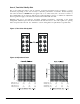
The recommended minimum side clearance between two units
is dimension “B’ in table on this page.
The unit must not be installed in a pit or enclosure that is
deeper or taller than the height of the unit unless extra space
is provided. The minimum clearance on each
side of the unit is dimension “C” in table on this page.
AIR
DISCHARGE
AIR
DISCHARGE
AIR
DISCHARGE
AIR FLOW AIR FLOW
AIR FLOW
“B”
AIR FLOW AIR FLOW
“C” “C”
IMM ACZ/AGZ-4 ACZ / AGZ-BM 5