
Operating instructions


ACZ Staging and Circuiting
All ACZ units have two circuits, each with either two compressors, or three compressors on models
ACZ 120 through 155. These circuits must be kept separated throughout the entire refrigerant piping
system. Each unit refrigerant circuit must be piped to a separate coil or to a separate air handler
(with a single coil).
Temperature control for each evaporator coil is provided by the installer through field-supplied and
wired temperature controllers. The field-supplied staging signals are field-wired to the Microtech II
controller that correspondingly activates and deactivates the scroll compressors. The MicroTech II
controller has a menu screen (See operating manual OM AGZ) that allows selection between “Unit’
and “Circuit”.
Select “Unit” for a single air handler with row control where it does not matter which circuit starts
first. When the controller gets a signal to start Stage 1 of cooling, it will start the compressor, on
either circuit, with the fewest number of starts, so either circuit can start first. Energizing stage 2
will start the compressor with the fewest starts on the other circuit. Further staging requests will
continue to start alternate compressors between the two circuits.
For applications where the staging must be associated with a particular circuit (face-split coils or
separate air handlers), select “Circuit”. In this mode, stages 1, 2, and 3 are connected to refrigerant
circuit #1 and stages 4, 5,and 6 to refrigerant circuit #2. As the thermostat for coil #1 stages up, the
microprocessor will start the compressors on circuit # 1 (compressors 1, 3 and 5). Compressors 5
and 6 are found only on the six compressor units.
The field supplied temperature controller is required to close normally open 24-volt contacts on a
demand for cooling. These closure signals are field wired to the terminal strip (TB3) in the
condensing unit. Refer to the field wiring diagram (page
51) for details. The following control
staging is required:
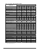
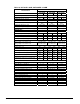
Number of Number of Required
Condensing Unit Model
Capacity Steps Contact Closure Signals
ACZ-030B through 110B 4 4
ACZ-120B through 155B 6 6
In summary:
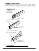
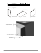
• Evaporator coil #1 must be piped to the condensing unit circuit #1. See dimension drawings
beginning on page
52. Evaporator coil #2 must be piped to the condensing unit circuit #2. See
dimension drawings beginning on page
52 for circuit locations.
• Evaporator staging thermostat for coil #1 must be wired to the unit terminal board TB3, stages 1,
and 2 (and 3 on models 120 through 155). Evaporator staging thermostat for coil #222 must be
wired to the unit terminal board TB3, stages 4, and 5 (and 6 on models 120 through 155).
IMM ACZ/AGZ-4 ACZ / AGZ-BM 21