Installation, Operation and Maintenance Manual IOMM ACZ1-2 Group: Chiller Part Number: 331373901 Effective: June 2005 Supersedes: IOMM ACZ1-1 Air-Cooled Scroll Condensing Units ACZ 010A – ACZ 039A 10 to 43 Tons, 35 to 150 kW R-22, R-407C 60 Hertz Software Version: ACZSU0102B
Table of Contents Introduction........................................3 Standard MicroTech II Controller. 25 General Description..........................................3 Inspection .........................................................3 Installation........................................................3 Handling...........................................................3 Location ...........................................................4 Service Access.............................................
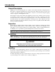
Introduction General Description McQuay air-cooled condensing units are complete, self-contained automatic refrigerating units. Every unit is completely assembled, factory wired, and tested. Each unit consists of an air-cooled condenser, Copeland Compliant Scroll£ hermetic compressor, and internal refrigerant piping, ready to be piped to a field supplied low side.
Figure 1, Suggested Pushing Arrangement Blocking required across full width Figure 2, Suggested Lifting Arrangement Location Unit Placement ACZ units are for outdoor applications and can be mounted on a roof or at ground level. Set units on a solid and level foundation. For roof-mounted applications, install the unit on a steel channel or I-beam frame to support the unit above the roof. For ground level applications, install the unit on a substantial base that will not settle.
Clearances The flow of air to and from the condenser coil must not be limited. Restricting airflow or allowing air recirculation will result in a decrease in unit performance and efficiency. There must be no obstruction above the unit that would deflect discharge air downward where it could be recirculated back to the inlet of the condenser coil. The condenser fans are propeller type and will not operate with ductwork on the fan outlet. Figure 3, Clearance requirements 4 Ft.
Vibration Isolators Vibration isolators are recommended for all roof-mounted installations or wherever vibration transmission is a consideration. The unit should be initially on shims or blocks at the listed free height. When all piping, wiring, flushing, charging, etc. is completed, the springs are adjusted upward to loosen the blocks or shims that are then removed. A rubber anti-skid pad is part of the isolator.
Chilled Water System Water Piping (Applicable when the Unit is Field Connected to a Water Type Evaporator) Local authorities can supply the installer with the proper building and safety codes required for proper installation. Install piping with minimum bends and changes in elevation to minimize pressure drop. Consider the following when installing water piping: 1. Vibration eliminators to reduce vibration and noise transmission to the building. 2.
System Volume It is important to have adequate water volume in the system to provide an opportunity for the chiller to sense a load change, adjust to the change and stabilize. As the expected load change becomes more rapid, a greater water volume is needed. The system water volume is the total amount of water in the evaporator, air handling products and associated piping.
Adjustment No Flow Maximum Adjustment Flow No Flow Lpm gpm Lpm gpm Lpm gpm Lpm 18.2 3.0 11.3 7.7 29.1 5.9 22.3 22.7 3.6 13.6 10.0 37.9 7.0 26.5 37.5 5.9 22.3 15.8 59.8 11.0 41.6 57.9 9.5 36.0 23.7 89.7 17.0 64.3 92.4 15.4 58.3 35.5 134.4 29.2 110.5 126.0 21.1 79.9 61.4 232.4 37.7 142.7 Refrigerant Piping Introduction Proper refrigerant piping can represent the difference between a reliable, trouble free system and months or years of inefficient, problematic performance.
b. The actual length in feet c. The equivalent length contributed by elbows, fittings, valves or other refrigerant specialties. ASHRAE Tables 2-10, 11 & 12 d. If a vertical riser exists including the trap at the coil, determine the minimum tons for the circuit. Add b and c above to obtain the total equivalent feet. Use the ASHRAE table for R22. Suction line selections are based upon the pressure equivalent of a 2ºF loss per 100 equivalent feet.
Figure 6, DX Coil Piping Condensing Unit Above Coil Hot gas bypass valve and solenoid valve located as close to condensing unit as possible. Condensing Unit Below Coil n ctio Su essor r ch Pit omp C To n ctio r Su esso r ch Pit omp C To Liquid to Coil Air Flo w Hot gas bypass valve and solenoid valve located as close to condensing unit as possible.
Liquid Lines Liquid lines are generally sized for 1 to 2 degree F line losses or their equivalent in pressure drop. Actual selection can vary based upon the pressure drop expected from refrigerant specialties such as solenoids, refrigerant driers, valves, etc. piping lifts or risers and the amount of condenser sub-cooling expected.
Unit Component Location Control Panel Removable Panel in This Area to Facilitate Field Piping Suction Connection Tandem Scroll Compressors Liquid Connection Optional Hot Gas Bypass Valve Control Layout and Operation Control Center All electrical controls are enclosed in a weather resistant control center with tool-locked, hinged access doors. The left-hand section contains the microprocessor controller and control input and output terminals.
Start-up and Shutdown Pre Start-up 1. The chilled-water system should be flushed and cleaned or air filters checked for cleanliness on DX systems. 2. Open all electric disconnects and check all electric connections for tightness. 3. Inspect all water piping for flow direction and correct connections at the evaporator or ductwork for tightness and completeness. 4. Verify that thermostat connections for two stages of control have been connected to unit terminals 23 / J5-ID7 and 28 / J5- ID-8. 5.
Equipment Protection Alarms The following conditions will shut down the unit and activate the alarm circuit: • No water or air flow • Low evaporator pressure • High condenser pressure • Motor protection system • Phase voltage protection (Optional) • Outside ambient temperature • Sensor failures The following alarms will limit unit operation: • • • • Condenser pressure stage down, unloads unit at high discharge pressures Low ambient lockout, shuts off unit at low ambient temperatures Low evaporator pressure
Physical Data Table 3, Physical Data, ACZ 010A through 020A ACZ MODEL NUMBER PHYSICAL DATA 010A 013A 016A 020A BASIC DATA Number Of Refrigerant Circuits 1 1 1 1 22.0 (10.0) 22.0 (10.0) 24.0 (10.9) 31.0 (14.1) Unit Operating Weight, Lbs. (kg) 73.6 x 46.3 x 50.8 (1869) x (1176) x (1289) 1000 (454) 73.6 x 46.3 x 50.8 (1869) x (1176) x (1289) 1000 (454) 73.6 x 46.3 x 50.8 (1869) x (1176) x (1289) 1220 (554) 73.6 x 46.3 x 50.8 (1869) x (1176) x (1289) 1340 (608) Unit Shipping Weight, Lbs.
Table 4, Physical Data, ACZ 025A through 039A ACZ MODEL NUMBER PHYSICAL DATA 025A 028A 033A 039A BASIC DATA Number Of Refrigerant Circuits Unit Operating Charge, R-22, Lb. (kg), Note 1 Cabinet Dimensions, LxWxH, In. Cabinet Dimensions, LxWxH, (mm) Unit Operating Weight, Lbs. (kg) 1 1 1 1 34.0 (15.4) 36.0 (16.3) 47.0 (21.3) 50.0 (22.7) 106.2x 46.3 x 50.8 106.2x 46.3 x 50.8 106.2x 46.3 x 58.8 106.2x 46.3 x 58.
Electrical Data Field Wiring Wiring must comply with all applicable codes and ordinances. Warranty is void if wiring is not in accordance with specifications. Copper wire is required for all power lead terminations at the unit. ACZ 010A through ACZ 039A units have single-point power connection. A single field supplied fused disconnect is required or it can be supplied as a factory-mounted option. The control transformer is factory mounted.
Table 6, ACZ 010A – 039A Compressor and Condenser Fan Motor Amp Draw Rated Load Amps ACZ Unit Size Volts 010A 208 230 460 575 013A 208 230 460 575 016A 208 230 460 575 020A 208 230 460 575 025A 208 230 460 575 028A 208 230 460 575 033A 208 230 460 575 039A 208 230 460 575 Compressors Locked Rotor Amps No. of Fan Mtrs Compressors Fan Motor (Each) No. 1 No. 2 No. 1 No. 2 Fan Motor (Each) 60 14.8 14.8 7.1 5.8 14.8 14.8 7.1 5.8 5.8 5.8 2.8 2.5 2 2 2 2 23.7 21.4 10.7 11.
Table 7, ACZ 010A – 039A Field Wiring Data, Single Point Power Wiring to Standard Power Block Terminal ACZ UNIT SIZE Volts 010A 208 230 460 575 013A 208 230 460 575 016A 208 230 460 575 020A 208 230 460 575 025A 208 230 460 575 028A 208 230 460 575 033A 208 230 460 575 039A 208 230 460 575 HZ.
Notes for “Electrical Data” 1. Field Fuse Size for recommended and maximum is based on use of a time-delay fuse. 2. Unit wire size ampacity (MCA) is equal to 125% of the largest compressor-motor RLA plus 100% of RLA of all other loads in the circuit including the control transformer. 3. Since the control transformer is furnished, no separate 115V power is required. 4. If a separate 115V power supply is used for the control circuit, the wire sizing amps is 10 Amps. 5.
Figure 7, ACZ 010A through 039A, Typical Field Wiring Diagram UNIT MAIN TERMINAL BLOCK DISCONNECT (BY OTHERS) GND LUG 3 PHASE TO COMPRESSOR(S) AND FAN MOTORS POWER SUPPLY NOTE: ALL FIELD WIRING TO BE INSTALLED AS NEC CLASS 1 WIRING SYSTEM WITH CONDUCTOR RATED 600 VOLTS FUSED CONTROL CIRCUIT TRANSFORMER 120 VAC DISCONNECT (BY OTHERS) TB1-20 N TB1 10A FUSE 120VAC CONTROL POWER CONTROL CIRCUIT FUSE 1 (BY OTHERS) LIQUID LINE SOLENOID 120 VAC 1.
Dimensional Data Figure 8, ACZ 010A through 020A 46.27 (1175.26) POWER ENTRY KNOCKOUT (OTHER SIDE) POWER ENTRY CONTROL PANEL ACCESS DOORS CONTROL ELECTRICAL KNOCKOUT 51.0 (1295.40) SUCTION INLET ACCESS DOOR HOT GAS BYPASS Z LIQUID OUTLET Y X 21.32 (541.53) 46.23 (1174.24) LIFTING SLOTS Liquid Conn. inches (mm) 010A, 013A 016A, 020A 7/8 (22.2) 7/8 (22.2) 7.55 (191.77) 3.94 (100.08) M0UNTING HOLES QTY. 4 01.00 (25.4) 49.06 (1246.12) 73.55 (1868.17) ACZ Unit Size 31.11 (790.
System Maintenance General On initial start-up and periodically during operation, it will be necessary to perform certain routine service checks. Among these are taking electric leg readings. Some readings are readily available on the MicroTech II display. Lubrication No routine lubrication is required on the ACZ units. The fan motor bearings are of the permanently lubricated type and require no lubrication. Electrical Terminals WARNING Electric shock hazard.
Standard MicroTech II Controller Table of Contents Overview ............................................................................ 26 General Description ............................................................ 26 Compressor Motor Description ...................................... 26 FanTrol Head Pressure Control ...................................... 26 Inputs/Outputs ............................................................... 27 Setpoints......................................................
Overview The MicroTech II controller's state-of-the-art design will not only permit the unit to run more efficiently but also simplifies troubleshooting if a system failure occurs. Every MicroTech II controller is programmed and tested prior to shipment to contribute to a trouble-free start-up.
Table 8, Fan Staging Pressures Fan Two-Fan Unit Three-Fan Unit Stage #1 Stage #2 Stage #3 On 150 psig, Off with unit On 290 psig, Off 170 psig On 150 psig, Off with unit On 290 psig, Off 170 psig On 310 psig, Off 180 psig Note: Fan #1 is on with first compressor above 75°F (24°C). Inputs/Outputs Table 9, Inputs and Outputs Analog Inputs # 1 2 3 4 5 Description Open Evaporator Refrigerant Pressure Condenser Refrigerant Pressure Open Outside Ambient Temperature Signal Source Range 0.5 VDC to 4.
Table 10, Setpoints Description Unit Unit Enable Available mode Control Source Air Flow Timer Low Ambient Lockout Refrigerant Type BAS Protocol Ident number Baud rate Evaporator Refrig Press Sensor Offset Condenser Refrig Press Sensor Offset Outside Ambient Temperature Sensor Password Compressor Clear Cycle Timers Start-Start Stop-Start Stage Up Delay Stage Down Delay Comp 1 Enable Comp 2 Enable Alarms Low Evap Pressure-Hold Low Evap Pressure-Unload Evap Flow Proof High Condenser Pressure High Condenser Sta
Dynamic Default Values Some setpoints will have different default values loaded depending on the value of other setpoints. Low Evaporator Pressure Inhibit Refrigerant R22 R407C Default Value 59 psi 60 psi Low Evaporator Pressure Unload Refrigerant R22 R407C Default Value 58 psi 59 psi Equipment Protection (Stop) Alarms Equipment protection (stop) alarms execute rapid compressor shutdown without going through the normal shutdown cycle.
Events (Limit Alarms) The following events limit the operation of the unit in some way as described in the Action Taken column. These alarms are auto-clearing based on reaching the conditions in the reset column.
Table 13, R-22 Saturated Temperatures o Pressure (psi) 24.0 34.7 47.6 62.8 80.8 101.6 126.2 153.8 185.2 220.6 260.5 305.2 355.1 430.4 Temperature ( F) 0 12.0 24.0 36.0 48.0 60.0 72.0 84.0 96.0 108.0 120.0 132.0 144.0 160.0 R407C Saturated Temperature Evaporator dew point and condenser mid point are calculated using 32 bit math.
Unit Mode The overall operating mode of the chiller is set by the Available Mode Setpoint with options of COOL and TEST. Unit Test Mode The unit test mode allows manual testing of controller outputs. Entering this mode requires the following conditions. • • • Unit Switch = OFF Manager password active. Available Unit Mode setpoint = TEST A test menu can then be selected to allow activation of the outputs. It is possible to switch each digital output ON or OFF and set the analog outputs to any value.
T2: Transition from Auto to Pumpdown Requires any of the following: • Keypad Enable = Off OR • BAS Enable = Off OR • Remote Switch = Off OR • Pumpdown Alarm Active T3: Transition from Pumpdown to Off Requires any of the following: • Unit Alarm OR • Unit Switch Off OR • All compressors off T4: Transition from Auto to Off Requires any of the following: • Unit Alarm OR • Unit Switch Off • Both compressors disabled via manual setpoint Evaporator Fan State Control Operation of the evaporator fan output is contr
Fan 3 will stop when the condenser pressure drops to the Stage #3 Off setpoint, and fan 2 will stop when the condenser pressure drops to the Stage #2 Off setpoint. Fan 1 will stop when the pressure drops down to the Stage #1 Off setpoint. Low OAT Start In order to avoid low-pressure alarms at startup, low OAT start logic allows for running at low pressures for a longer time than normal as well as multiple start attempts.
Low Ambient Lockout If the OAT drops below the low ambient lockout setpoint, the unit will do a normal stop. Once the lockout has been triggered, no compressors will start until the OAT rises to the lockout setpoint plus 5°F.
Compressor State A compressor will start when all of the following are true: • The compressor is “next on” • Stage Up Now is set • The compressor is available to start A compressor will stop when any of the following conditions are true: • Unit state = Off • Evap flow alarm active • Low Ambient start attempt failed • Stage Down Now is set, both compressors are running, and the compressor is “next off” • Pumpdown is complete Normal Shutdown If a condition arises that requires the unit to shut down, a pumpdo
Using the Controller 4x20 Display & Keypad Layout The 4-line by 20-character/line liquid crystal display and 6-key keypad are shown below. Figure 12, Display (in MENU mode) and Keypad Layout Key to Screen Pathway Red Alarm Light MENU Key Air Conditioning < ALARM VIEW < SET < ARROW Keys ENTER Key Note that each ARROW key has a pathway to a line in the display. Pressing an ARROW key will activate the associated line when in the MENU mode.
MENU Key The MENU key is used to switch between the shortcut method (known as the MENU mode and as shown in Figure 12) and scrolling method (known as the SCROLL mode). The MENU mode is the shortcut to specific groups of menus used for checking ALARMS, for VIEWING information, or to SET setpoint values. The SCROLL mode allows the user to move about the matrix (from one menu to another, one at a time) by using the four ARROW keys. A typical menu screen is shown in Figure 13.
Most menus containing setpoint values have several different setpoints shown on one menu. When in a setpoint menu, the ENTER key is used to proceed from the top line to the second line and on downward. The cursor will blink at the entry point for making a change. The ARROW keys (now in the edit mode) are used to change the setpoint as described above. When the change has been made, press the ENTER key to enter it. No setting is changed until the ENTER key is pressed.
Figure 14, Menu Matrix "MENU" "VIEW" MENUS REFRIGERANT FANS VIEW UNIT UNIT VIEW UNIT VIEW COMP #1 COMP VIEW COMP #2 VIEW EVAP/COND PRESS VIEW STATUS 1-3 TEMP STATUS 1-2 STATUS 1-2 1-2 FANS ⇐ Continued ⇐ (Right side of matrix continued from above) "ALARM" MENUS ALARM LOG "SET" MENUS EVENT LOG ACTIVE ALARM SET UNIT SPs, (1) MODE (LAST) (LAST) (1) TYPE, TIME TYPE, TIME TYPE, TIME ALARM LOG EVENT LOG ACTIVE ALARM SET UNIT SPs, (NEXT TO LAST) SET FANS (1) SET COMP SET LIMIT SPs (1)
menu item is selected, the display changes to the selected data screen. An example follows showing the selection of the “VIEW REFRIGERANT” screen. Suppose the initial screen is as below or any other menu screen: ALARM LOG (data) (data) (data) After pressing the MENU key, the top level menu screen will show: < ALARM < VIEW < SET After pressing the “VIEW” menu key, a menu screen will show: VIEW < UNIT < COMPRESSOR < REFRIGRANT < FANS Selection of any of these will advance to the appropriate data menu.
VIEW UNIT STATUS (3) D.O D.I. 12345678 12345678 00000000 00000000 View Unit Temperatures VIEW UNIT TEMP °F Outside Amb = XX.X°F VIEW COMPRESSORS VIEW COMP#1 (1) State = OFF LEAD Cycle Timer: XXmin Manual Disable Cycle timer only visible when active. Manual Disable visible only when compressor is disabled via manual enable setpoint. VIEW COMP#1 Hours = XXXXX Starts = XXXXX (2) Above two screens duplicated for Compressor #2. VIEW REFRIGERANT VIEW REFRIG (1) EVAP Press = XX.Xpsi COND Press - XX.
VIEW FANS VIEW FANS Stages ON = 2 of 3 Screen Definitions – ALARM ALARM ACTIVE (X) ALARM ACTIVE (X) Alarm Description No more alarms hh:mm:ss dd/mmm/yyyy Press ENTER to clear all active alarms If the unit is off on a shutdown alarm or running but in a limit alarm condition, the cause and date will appear in the upper screen. If there is a simultaneous occurrence of more than one alarm, the others will appear in additional screens below this one, accessed by the DOWN ARROW.
SET UNIT SPs SET UNIT SPs (1) Unit Enable=OFF Source=KEYPAD Unit Enable is an external signal or a keypad setting that keeps the unit off when the setting is OFF and allows it to run if there is a call for cooling. The source for the signal is selected in the 3td line and can be: 1. KEYPAD, in which case the selection is made in line 2 and would be normally selected as ON. This is the normal setting when no external signals are controlling the unit. 2.
SET UNIT SPs (7) Evaporator Refrig Press Sensor Offset= 00.0 psi The pressure offsets on menus 7 and 8 and the temperature offset on menu 9 correct the controller's display of the parameters. The sensors used in these units have a high degree of repeatability but may need correction (offset). An accurate pressure gauge or thermometer is used to determine the correct temperature or pressure. A positive or negative offset value is then entered to make the controller reading agree with the measured value.
InterStageUp is the time delay since the last stage change before a compressor can stage on. InterStageDn is the time delay since the last stage change before a compressor can stage off normally (not by an alarm). SET COMP SPs (3) Manual Comp Enable Comp 1= Enable Comp 2= Enable SET ALARM SETPOINTS SET ALARM LMTS (1) Low Evap Pressure Hold = 59.0 psi Unload = 58.0 psi If two compressors are running, the LowEvPr Unld is in effect and the lag compressor will be shut off to unload the unit.
SET FANS SETPOINTS SET FANS SPs (1) Fans Stages = X Speedtrol = NO The Fan Stages line tells the controller the number of fans on the unit. The UP ARROW toggles between 1, 2, and 3. 1 is not used; 2 should be used for Models ACZ 010, 013, and 017; and 3 should be used for ACZ 020, 025, 029, and 039. SpeedTrol tells the controller whether the optional SpeedTrol is installed in the unit. The UP ARROW toggles between YES and NO.
Service DANGER Disconnect and tag-out all sources of power to the unit before doing any service inside the unit. Failure to do so can cause serious personal injury or death. CAUTION Service on this equipment must be performed only by trained, experienced, qualified service personnel with special regard to regulations concerning release of refrigerant to the atmosphere. Note: Repeated tripping of equipment protection controls must be investigated and corrected.
Optional Controls SpeedTrol Head Pressure Control The SpeedTrol method of head pressure control operates in conjunction with FanTrol by modulating the motor speed on system #1 fan in response to condenser pressure. By reducing the speed of the last fan as the condensing pressure falls, the unit can operate to 0°F (-18°C) ambient air temperature. The SpeedTrol fan motor is a single-phase, 230/460 volt, thermally protected motor specially designed for variable speed operation.
WARNING The hot gas line can become hot enough to cause injury in a very short time. Do not allow prolonged contact during valve checkout. On installations where the condensing unit is remote from the evaporator, it is recommended that the hot gas bypass valve be mounted near the condensing unit to minimize the amount of refrigerant that will condense in the hot gas line during periods when hot gas bypass is not required.
Troubleshooting Chart WARNING Troubleshooting must be done only by trained, experienced technicians. Troubleshooting presents risks of severe personal injury and death from cuts, burns, electrocution and suffocation.
Post Office Box 2510, Staunton, Virginia 24402 USA • (540) 248-0711 • www.mcquay.