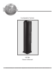
Loudspeaker System XRT2K Owner’s Manual McIntosh Laboratory, Inc.
WARNING - TO REDUCE RISK OF FIRE OR ELECTRICAL SHOCK, DO NOT EXPOSE THIS EQUIPMENT TO RAIN OR MOISTURE. NO USER-SERVICEABLE PARTS INSIDE. REFER SERVICING TO QUALIFIED PERSONNEL. To prevent the risk of electric shock, do not remove cover or back. No user serviceable parts inside. IMPORTANT SAFETY INSTRUCTIONS! PLEASE READ THEM BEFORE OPERATING THIS EQUIPMENT. 1. Read these instructions. 2. Keep these instructions. 3. Heed all warnings. 4. Follow all instructions. 5. Do not use this apparatus near water. 6.
Safety Instructions Thank You Table of Contents Your decision to own this McIntosh XRT2K Loudspeaker System ranks you at the very top among discriminating music listeners. You now have “The Best.” The McIntosh dedication to “Quality,” is assurance that you will receive many years of musical enjoyment from this unit. Please take a short time to read the information in this manual. We want you to be as familiar as possible with all the features and functions of your new McIntosh. Safety Instructions ......
Introduction For the first time, the new McIntosh XRT2K Loudspeaker System is capable of reproducing the full dynamic range of a symphony orchestra including pipe organ without audible distortion. McIntosh Acoustic Engineers have refined the line source Column Loudspeaker concept and the XRT2K Loudspeaker System is the 6th in a generation of that patented design1. It provides superior quality midrange and high frequency sound reproduction in a full range system.
Introduction and Performance Features tem weight to a minimum while preserving the utmost in performance. • Shielded Magnetic Field The XRT2K may also be used in Home Theater Installations near a television receiver or monitor without causing the television image to degrade. By design, all of the speakers’ magnetic structures are inherently shielded which prevents interference. Figure 6 low pass sums to a fourth order Linkwitz-Riley.
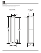
Dimensions The following dimensions can assist in determining the best location for your XRT2K Loudspeaker System. Front View of the XRT2K Loudspeaker System Side View of the XRT2K Loudspeaker System 14-15/32" 9-1/2" 36.75cm 24.13cm 2-17/32" 6.43cm 83-7/8" 213.04cm 80-9/16" 204.63cm 3-3/8" 8.57cm 19" 48.26cm 6 18" 45.
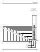
Dimensions Rear View of the XRT2K Loudspeaker System 48-1/16" 122.08cm 44-5/32" 112.16cm 41-1/16" 104.30cm 37-5/32" 94.38cm 34-23/32" 88.19cm 26-25/32" 68.02cm 24-11/32" 61.83cm 16-13/32" 41.67cm 13-15/16" 35.40cm 6-1/32" 15.32cm 7-3/16" 18.26cm 11-13/16" 30.
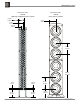
Dimensions, con’t Front View of the XRT2K Midrange and High Frequency Column 6-9/16" 16.67cm Front View of the XRT2K Low Frequency Column 7-1/2" 19.05cm 4-3/4" 12.07cm 2-15/16" 7.46cm 12-3/4" 32.39cm 49-1/2" 125.73cm 1-3/4" 4.45cm 2-3/16" 5.56cm 9-1/4" 9-9/32" 23.50cm 8 23.57cm 12-3/4" 32.39cm 10-1/4" 26.
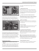
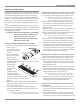
Unpacking and Assembly Unpacking and Assembly Follow the instructions below for unpacking and assembling the XRT2K Loudspeaker System. To protect the fine finish of the XRT2K Loudspeaker System during the assembly process, it is advisable to prepare a suitable assembly area. A freshly vacuumed carpeted area covered with a soft, clean fabric, such as a large bed linen or blanket would be suitable. Start by unpacking the Midrange/High Frequency Column.
Low Frequency Column (Upper Section). Refer to figure 3. 3. Carefully push Upper Woofer together the Column two Low Socket and Cable Midrange/Tweeter Column in cloth cover Figure 6 Lower Woofer Column Openings for pins HEX Head Bolts Figure 3 Frequency Columns (Lower and Upper Sections). 4. Using the socket tool, tighten the four hex head bolts until the Low Frequency Column (Lower and Upper Sections) is pulled together with no space between the two sections. Final Assembly of the Loudspeaker 1.
Room Placement Room Placement Loudspeaker placement in a room can greatly affect performance. The XRT2K Loudspeaker is designed for both Music and Home Theater Systems. The optimal method for selecting speaker locations includes the use of a real time spectrum analyzer operated by an experienced system installer.
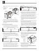
Midrange/Tweeter Column Rear Panel and Low Frequency Column Base Connections The 16 pin plug and cable at the front bottom of the LOW Frequency Column Base connects to the MIDRANGE/ HIGH Frequency Column 16 pin Connector MIDRANGE/HIGH Frequency Column 16 pin Connector, connects to the 16 pin plug and cable coming from the LOW Frequency Column Base 12
Low Frequency Column Rear Panel Connections Low Frequency Column Lower Section Connections connect to the Low Frequency Column Upper Section Connections. Note: Do not operate the XRT2K Loudspeaker System unless the Low Frequency Column Lower and Upper sections are connected together. 1 2 HIGH Frequency Input Connections 1, 2, and 3 for a 8 ohm Loudspeaker. Note: 1, 2 and 3 Terminals (+) are internally connected together; 1, 2 and 3 Terminals (-) are also internally connected together.
How to Connect using a single Amplifier Caution: The AC Power Cord should not be connected to the Power Amplifier until after the Loudspeaker Connections have been made. Failure to observe this could result in Electric Shock. 1. Prepare two 14 inch (35.6cm) Jumper Wires for connecting the Low Frequency Column, Lower and Upper Sections together by choosing one of the methods below: Bare wire cable ends: Carefully remove sufficient insulation from the cable ends, refer to figures 12, 13 & 14.
How to Connect using a single Amplifier 14 inch (35.
How to Connect using two Amplifiers Caution: The AC Power Cord should not be connected to the Power Amplifier until after the Loudspeaker Connections have been made. Failure to observe this could result in Electric Shock. 1. Prepare two 14 inch (35.6cm) Jumper Wires for connecting the Low Frequency Column, Lower and Upper Sections together by choosing one of the methods below: Bare wire cable ends: Carefully remove sufficient insulation from the cable ends, refer to figures 12, 13 & 14.
How to Connect using two Amplifiers 14 inch (35.
How to Connect using three Amplifiers Caution: The AC Power Cord should not be connected to the Power Amplifier until after the Loudspeaker Connections have been made. Failure to observe this could result in Electric Shock. 1. Prepare two 14 inch (35.6cm) Jumper Wires for connecting the Low Frequency Column, Lower and Upper Sections together by choosing one of the methods below: Bare wire cable ends: Carefully remove sufficient insulation from the cable ends, refer to figures 12, 13 & 14.
How to Connect using three Amplifiers 14 inch (35.
20
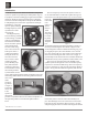
Photos 21 21
Specifications Specifications General Specifications System Driver Complement Six 12 inch Aluminum Cone Woofers Sixty-four 2 inch Titanium Inverted Dome Midranges Forty 3/4 inch Titanium Dome Tweeters Finish Enclosures High Gloss Black Aluminum Sides, Brushed Aluminum Front and Back, High Gloss Black Top and Bottom Impedance 8 ohms Nominal Frequency Response 16Hz - 45kHz Sensitivity 89dB (2.
Packing Instructions Packing Instructions In the event it is necessary to repack the equipment for shipment, the equipment must be packed exactly as shown below. To protect the finish of the Columns it is advisable to place them in the original protective cotton blue covers before placing them into the shipping carton. Use the original shipping carton and interior parts only if they are all in good serviceable condition.
Notes McIntosh Laboratory, Inc. 2 Chambers Street Binghamton, NY 13903 The continuous improvement of its products is the policy of McIntosh Laboratory Incorporated who reserve the right to improve design without notice. Printed in the U.S.A. McIntosh Part No.