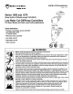
INSTRUCTION MANUAL MM-217L
CAUTION: • A more frequent replacement interval may be necessary based on the condition of the unit at time of inspection. McDonnell & Miller' s warranty is one (1) year from date of installation or two (2) years from the date of manufacture. OPERATION Maximum Pressure: 150 psi (10.5 kg/cm2) Electrical Ratings PumpCircuit Rating (Amperes) Full Load Locked Rotor 7.4 44.4 3.7 22.
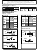
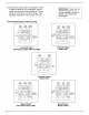
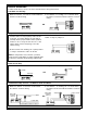
Settings and Differential Pressures (continued) Values are ± 8” (3.2mm). Model 158S Pressure 0 psi (0 kg/ cm2) Model 158S-MD Approximate Distance Above Cast Line Differential In. (mm) In. (mm) Setting Motorized Valve Closed Motorized Valve Open 15/16 5/8 (16) Burner On Burner Off 5/8 (16) (6.4) 1/4 Motorized 13/8 Valve Closed 150 psi 5/8 (10.5 kg/ Motorized Valve Open cm2) 7/8 Burner On Burner Off 0 150 psi (10.
Settings and Differential Pressures (continued) Values are ± 8” (3.2mm). Model 159S Setting Pressure 0 psi (0 kg/ cm2) Approximate Distance Above Cast Line Differential In. (mm) In. (mm) Pump #1 Off Pump #1 On 15/16 Pump #2 Off Pump #2 On 5/8 5/8 1/4 (24) (16) 5/16 (8) (16) (6.4) 3/8 (16) 3/4 (19) 7/8 (22) Pump #1 Off 13/8 (41) 5/8 (16) 150 psi Pump #1 On (10.5 kg/ Pump #2 Off cm2) Pump #2 On 7/8 (22) (0) 0 150 psi (10.
INSTALLATION TOOLS NEEDED: Two (2) pipe wrenches, one (1) flathead screw driver, and pipe sealing compound. IMPORTANT: Follow the boiler manufacturer's instructions along with all applicable codes and ordinances for piping, blow down valve and water gauge glass requirements.
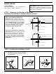
Models 150S-B b. For Model 150S-B and Series 157S (For all other models, proceed to Step 3). C Series 157S C A Screw the w” NPT steel plug (C) (provided) in tapping (A). A ! CAUTION The plug must be reinstalled before control is shipped installed on the boiler, and removed when boiler is installed after shipment. Failure to follow this caution may damage float and operating mechanism. c.
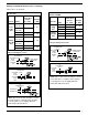
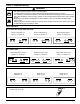
STEP 4 - Electrical Wiring ! WARNING • To prevent a fire, do not use this product to switch currents over 7.4A, 1/3 Hp at 120 VAC or 3.7A, 1/3 Hp at 240 VAC, unless a starter or relay is used in conjunction with it. • To prevent electrical shock, turn off the electrical power before making electrical connections. • This low water cut-off must be installed in series with all other limit and operating controls installed on the boiler.
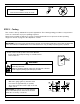
WIRING DIAGRAMS For Motorized Valves, refer to the valve manufacturer's wiring instructions. Low Water Cut-Off Only 2. Pilot Switch - To holding coil of a starter when the burner circuit exceeds the switch’s electrical rating. 1. Main Line Switch - For burner circuits within the switch’s electrical rating. LINE LINE LOAD 1 2 OR 4 5 6 1 2 4 5 6 LOAD Pump Control Only NOTE: For Model 159S, use terminals 5 and 6 from starter or relay for pump # 2. 1.
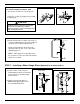
6. Re-attach the junction box cover (K). K Note: Cover must be installed correctly as shown STEP 5 - Testing This control is factory calibrated for specific applications. The following testing procedure is only meant to serve as a verification of proper operating sequence. Dimensions provided are typical for a boiler not being fired and/or not at pressure. Actual operating ranges are shown on page 2 in the "Operation" section.
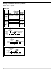
c. For automatic reset models only. When the water level reaches approximately d” (22mm) above the horizontal cast line (lower for MD models) the burner should come on (pump #2 should shut off with Model 159S). Snap Switch Models N OR For manual reset models only. When the water level reaches approximately d” (22mm) above the horizontal cast line press the reset button (N). The burner should then come on. d.
Xylem Inc. 8200 N. Austin Avenue Morton Grove, Illinois 60053 Phone: (847) 966-3700 Fax: (847) 965-8379 www.mcdonnellmiller.com McDonnell & Miller is a trademark of Xylem Inc. or one of its subsidiaries. © 2014 Xylem Inc. MM-217L September 2014 Part No.