
Install Instructions

4
A
B
C
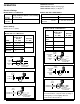
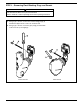
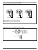
a. Mount and pipe the control (A) on vertical equalizing
pipes (B) at the required elevation as determined in
Step 1.
Install a full-ported blow-down valve (C) directly
below the lower cross.
NOTE:
1” (25mm) NPT tappings are provided on Series
93/193 controls.
1 1/4” (32mm) NPT tappings are provided for Series
94/194 controls and 193-B Model.
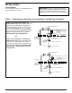
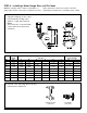
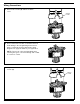
STEP 2 - Installing the Low Water Cut-Off/Pump Controller
For Series 93/193 or 94/194 (except 94-A, 193-D and 193-G Models)
A
E
C
D
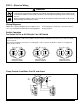
a. Mount and pipe the control (A) with a vertical upper
(D) and horizontal lower (E) equalizing piping at the
required elevation as determined in Step 1.
Install a full-ported blow-down valve (C) on the lower
body connection.
NOTE:
1 1/4” (32mm) NPT tappings are provided for 94-A
Model control.
1” (25mm) NPT tappings are provided for 193-G
Model control.
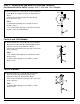
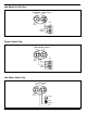
For 94-A and 193-G Models
A
C
G
a. Mount and pipe the control (A) with a horizontal
upper and lower (G) equalizing piping at the
required elevation as determined in Step 1.
Install a full-ported blow-down valve (C) on the lower
body connection.
NOTE:
1” (25mm) NPT tappings are provided for 193-D
Model control.
For 193-D Models